
- Introduction
- Before you start
- Getting Help
- Default Credentials
- Package Contents
- System Overview
- Revealing the Windows Product Key
- Rackmount Installation
- Hard Drive Installation
- Connect Cables
- Log Into Windows For The First Time
- Checking RAID Health
- Video Management Software
- Windows Activation Without Internet Access
- MegaRAC SP-X BMC
- Maintenance
Introduction #
The system may take up to 15 minutes to complete the power on self-test (POST) during the first power up.
During this time, the screen may remain blank. After a few minutes the message “Please wait for chipset initialize…” will be displayed.
This is normal—please do not interrupt or power off the system during this process.
Arxys VideoX V5 Appliances are Network Video Recorders (NVRs) preloaded with Microsoft Windows Server operating system. Arxys VideoX V5 Appliances are configured for ease of use by video surveillance integrators. VideoX V5 Appliances products have been tested with various VMS solutions and offer unparalleled value and performance.
This administrator manual applies to the following models:
| VX5-V400-112 | VX5-V400-128 | VX5-V400-144 | VX5-V400-160 |
| VX5-V400-176 | VX5-V400-192 |
Before you start #
The proper installation of the Arxys VideoX V5 Appliances will require the following hardware and resources:
- Keyboard and mouse.
- Display monitor capable of 1024×768 resolution with a Standard VGA connector
- Two 110V-240VAC power ports (Preferably on different sources, UPSs, or circuits)
- Gigabit Ethernet connectivity
- Network IP address
- Available space in a computer equipment rack
- Available ports in an uninterruptable power supply (UPS).
V400 Maximum Video Stream Rate (Max VSR) #
The maximum video stream rate (Max VSR) is the maximum camera streams that an Arxys NVR can process using our standardized “VSR” parameters for both h.264 and h.265 compression without exceeding 75% of the compute capabilities of the NVR.
The Max VSR of VX5-V400 is 200 streams
The standardized parameters per stream of Max VSR are:
- Resolution: 4MP – 2560 x 1440
- Frame Rate: 15 frames per second (FPS) or 15 image per second (IPS)
- Codec and Complexity: h264.20 (good quality) or h265.20 (good quality)
- Motion Activity: 75% motion
- Analytics: standard motion detection and metadata capture
- Retention: 30 days (18 hours per day per camera)
Exceeding these parameters may cause a suboptimal experience.
| Resolution | h264 streams | h265 streams |
|---|---|---|
| 1920 x 1080 | 300 | 200 |
| 2560 x 1440 (Max VSR) | 200 | 200 |
| 3840 x 2160 | 120 | 120 |
Networking #
It is recommended that cameras not be connected to the appliance until after the appropriate network configuration has been set up. Some Video Management Software (VMS) supports bonded or aggregated networking. Do not configure bonded or aggregated networking if the VMS does not support network redundancy. Verify with the network administrator that multicast has been properly configured.
Uninterruptable Power Supply #
A UPS system in an integral part of any deployment and offers protect from power issues such as; unclean power, overvoltage, undervoltage, and power loss. The UPS should be configured to signal the operating system to cleanly power off the VideoX V5 NVR when the battery power dips below the safe threshold.
Any UPS connection must include configuration to shut down the operating system on the appliance when battery power is low or there is 15 minutes of power remaining.
Dimensions #
Width x Depth x Height
438 x 680 x 88 millimeters
Power Usage #
The power usage listed below were measured under an typical NVR use case using a 120 VAC 60Hz power source. Actual power usage will vary depending on many factors.
| VX5-V400 w/ 8x HDDs 120 VAC | Current (Amps) | Power (Watts) |
|---|---|---|
| Idle | 1.1 | 195 |
| High Load | 2.2 | 285 |
| Startup Peak Power | 3.0 | 400 |
| Power Supply Maximum | 10 | 800 |
The power usage listed below were measured under an typical NVR use case using a 208 VAC 60Hz power source. Actual power usage will vary depending on many factors.
| VX5-V400 w/ 8x HDDs 208 VAC | Current (Amps) | Power (Watts) |
|---|---|---|
| Idle | 0.8 | 190 |
| High Load | 1.2 | 285 |
| Startup Peak Power | 1.8 | 400 |
| Power Supply Maximum | 5 | 800 |
Getting Help #
For questions and support regarding the Arxys VideoX Enterprise Appliance hardware, please contact Arxys using the following options:
Web: https://support.arxys.com/
Hours: Monday – Friday, 8:00 a.m.–5:00 p.m. (Pacific time) Holidays Excluded
Web page: https://www.arxys.com/company/support
The primary method to receive help and support for Arxys VideoX Appliances is through the online ticket system.
Opening A Ticket #
For information on opening a ticket with Arxys see https://www.arxys.com/docs/starting-ticket/
System Serial Number Location #
The Arxys VideoX V5 Appliance will have a label with both the system serial number and unique MegaRAC SP-X BMC password on the front top right hand corner of the system.
Default Credentials #
Windows Operating System #
The Windows operating system administrator password is configured by the end user during the first boot setup procedure.
Do not lose or misplace this password. The password configured by the end user cannot be reset by Arxys.
LSA Storage Authority #
The default user name and password for LSA Storage Authority
MegaRAC SP-X BMC (IPMI) Credentials #
Each Arxys VideoX V5 Appliance has a unique MegaRAC SP-X BMC password for the “admin” user. The unique password will be listed on the system serial number label. Additionally on certain models the unique password will be on the front system pull tab.
Arxys HIGHLY recommends that this password also be changed to a unique password known only to system administrators to prevent unauthorized access to the Arxys VideoX V5 Appliance MegaRAC SP-X BMC module.
Package Contents #
- Arxys VX5-V400 NVR
- 8x Hard Disk Drives (HDDs)
- Sliding Rack Rail kit
- Power Cables
System Overview #
Front View #
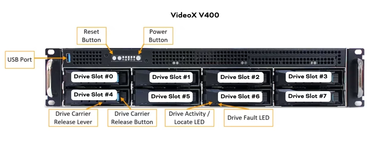
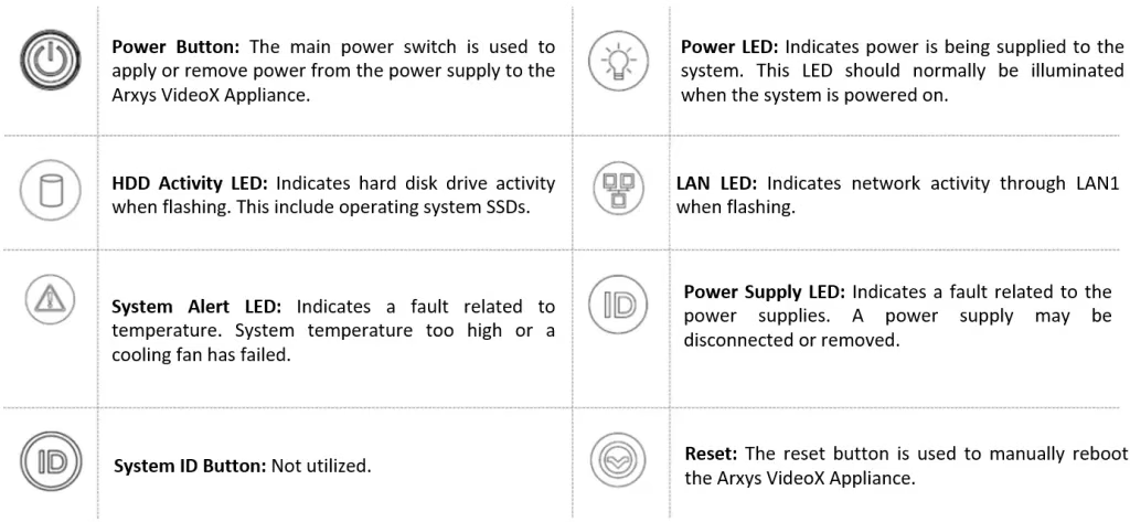
Front Panel LEDs and buttons #
Hard Drive LEDs #
| Indicator | Behavior | Description |
| HDD Activity LED | Solid Blue | HDD is present and powered on |
| Blinking Blue | HDD activity detected | |
| Off | HDD is not present | |
| HDD Status LED | Solid Red | HDD Failure |
| Blinking Red | HDD maintenance operating in progress | |
| Off | HDD in normal operating mode |
If the hard drive LEDs are solid blue with blinking red, without any of the drives having a solid red LED, the system is performing a consistency check or patrol read on the hard drives. This is normal and can be confirmed in LSA. Try not to interrupt the system by restarting it as this will cause the consistency check to restart.
Rear View #
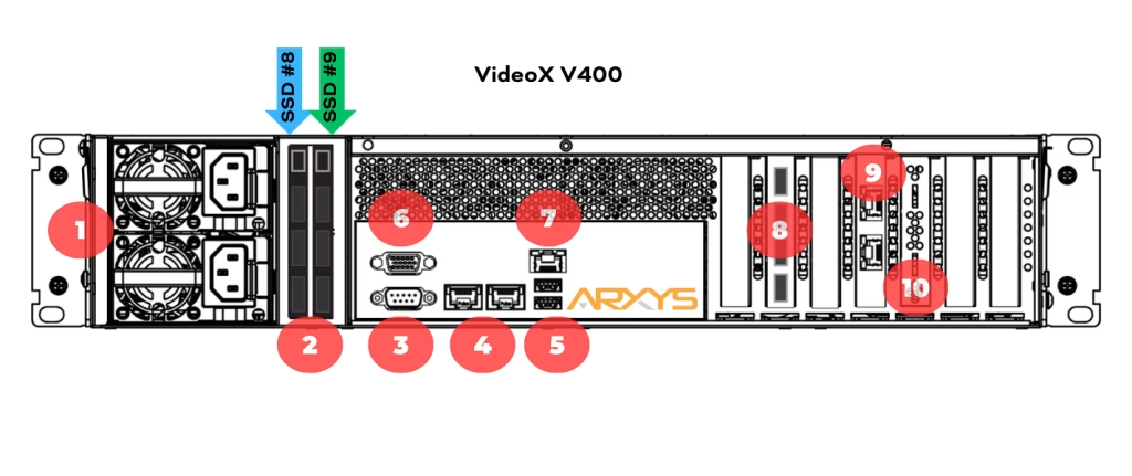
| Figure Number | Item Name | Description |
|---|---|---|
| 1 | Power Supplies | Auto ranging for 110-240 VAC. 1+1 redundant hot swap configuration |
| 2 | Two Operating System SSDs | Solid state drives configured in RAID 1 (Mirror) |
| 3 | Video Connector | The VGA connector should be used for initial setup and deployment. |
| 4 | 10Gb/s LAN ports 1 and 2 | Accepts Ethernet connections from two networks at speeds up to 10 gigabits. Link LED: Yellow = 5 Gb/s, 2.5 Gb/s, 1Gb/s. Green = 10Gb/s. Off = 100 Mb/s |
| 5 | 2 x USB 3.2 Gen1 ports | For keyboard and mouse use. Also used to factory restore systems. It should NOT be used for storage expansion |
| 6 | Serial port | RS232 for UPS communication. |
| 7 | Dedicated Management LAN (BMC) | Dedicated out of band management for BMC |
| 8 | Video Analytics Accelerator (Optional) | Can be used to enable or accelerated video analytics of various VMS. See VMS documentation for specifics |
| 9 | 10Gb/s LAN ports 3 and 4 | Accepts Ethernet connections from two networks at speeds up to 10 gigabits. Link LED: Yellow = 5 Gb/s, 2.5 Gb/s, 1Gb/s. Green = 10Gb/s. Off = 100 Mb/s |
| 10 | RAID Controller | Virtualizes drives into drive groups with additional data protection. RAID level 6 recommended. |
| SSD #0 | Rear Slot 0 | Hot swap slot #8 |
| SSD #1 | Rear Slot 1 | Hot swap slot #9 |
Revealing the Windows Product Key #

The product key is found on the Microsoft® Certificate of Authenticity (COA) label located on the front left corner of the appliance. Similar to the removable material commonly found on lottery tickets or prize vouchers, this concealment panel is designed to protect the consumer’s product key from being obtained and used by unauthorized individuals. Carefully scratch off the concealment coating with a fingernail or coin to reveal the entire product key.
Copy down the 25 digit product key or take a picture. The product key will need to be typed in on order to activate the system.
Rackmount Installation #
- Install the largest and heaviest items on the bottom of your rackmount rack.
- Ensure that the leveling jacks on the bottom of the rack are fully extended to the floor with the full weight of the rack resting on them and not the casters.
- In single rack installation, stabilizers should be attached to the rack. In multiple rack installations, the racks should be coupled together.
- Always make sure the rack is stable before extending a component from the rack.
- You should extend only one component at a time – extending two or more simultaneously may cause the rack to become unstable.
- Determine the placement of each component in the rack before you install the rails.
- Use a regulating uninterruptible power supply (UPS) to protect the server from power surges, voltage spikes and to keep your system operating in case of a power failure.
- Always keep the rack’s front door and all panels and components on the servers closed when not servicing to maintain proper cooling.
- Equipment should be mounted into a rack so that the amount of airflow required for safe operation is not compromised.
- Consideration should be given to the connection of the equipment to the power supply circuitry and the effect that any possible overloading of circuits might have on overcurrent protection and power supply wiring. Appropriate consideration of equipment nameplate ratings should be used when addressing this concern.
Rail Kit Installation #
This section provides information on installing the Arxys VideoX V5 Appliance into a server rack with the quick-release rails provided. There are a variety of rack units on the market, which may mean the assembly procedure will differ slightly. You should also refer to the installation instructions that came with the rack unit you are using.
NOTE: This rail will fit a rack between 26.5″ and 36.4″ deep.
The Arxys VideoX V5 Appliances should be installed into the rack without hard disk drives installed.
There are two rack rail assemblies in the rack mounting kit. Each assembly consists of two sections: an inner fixed chassis rail that secures directly to the server chassis and an outer fixed rack rail that secures directly to the rack itself. Two pairs of short brackets to be used on the front side of the outer rails are also included.
Inner Rails #

- Unbox the rail kit
- Pull the inner rail out of the outer rail (1) until it is fully extended.
- Pull forward on the locking mechanism (2) to release the inner rail and pull the inner rail out of the outer rail

- Press the inner rail tightly against the chassis and slide the inner rail backwards until it clicks into the locked position.
- Secure the inner rails to the chassis with the one of the short pan head fasteners provided on each side.
- Repeat steps 1-5 for the other side.

Outer Rails #

- Press down on the (3) locking bar on the middle rail and slide (4) the middle rail back into the outer rail. While installing the rails into the rack make sure the middle rail is fully retracted into the outer rail.
- While making sure the middle rail is fully retracted into the outer rail, align (5) the square pins press the front of the outer rail against the corresponding square holes in the rack. The locking latch will click and hold the rails in place.
- Extend the rear section of the outer rail as required to reach the rear of the rack. This time align (6) the square pins press the rear of the outer rail against the corresponding square holes in the rack. The locking latch will click and hold the rails in place.
- The rails MUST be secure with fasteners. Use the larger fasteners provided if appropriate for the rack be being used to secure the outer rail to the rack.
- Verify that the rail is level and not bowed in either direction
- Repeat steps 1-5 for the other side.

Installing the Chassis in the rack #

- Confirm that the inner rails are properly installed on the chassis.
- Confirm that the outer rails are correctly installed on the rack.
- Pull the middle rail out from the front of the outer rail and make sure that the ball-bearing shuttle is at the front locking position of the middle rail.
- Align the chassis inner rails with the front of the middle rails.
- Slide the inner rails on the chassis into the middle rails, keeping the pressure even on both sides, until the locking tab of the inner rail clicks into the front of the middle rail, locking the chassis into the fully extended position.
- Depress the locking tabs of both sides at the same time and push the chassis all the way into the rear of the rack.
- The chassis MUST be secured to the rack with fasteners. Use the appropriate fasteners provided recommend by the rack manufacturer.
Hard Drive Installation #
Arxys VideoX V5 Appliance are shipped without the hard drives installed in the system chassis. Before powering on the Arxys VideoX V5 Appliance, the hard drives need to be installed into the chassis.
Before proceeding, verify that the hard drives are labeled with the same serial number listed on the Arxys VideoX V5 Appliance which is located on the front right corner of the chassis.
The Arxys VideoX V5 Appliance chassis features a label listing the arrangement of its hard disk drive slots. This label ONLY provides a general pattern for the sequential installation of the hard drives (beginning left to right, and then moving down to the next row). These labels can also be used in the troubleshooting process to identify the location of a faulty drive.
Unless marked any drive can be installed in any hard disk drive slot.

- Press the release button on the drive carrier. This extends the drive carrier handle.
- Insert the hard drive and tray into the chassis
- Press the drive firmly into the chassis
- Swing the drive carrier handle towards the system until closed until it clicks and locks in place.
- Repeat step one and two for all the drives shipped with the Arxys VideoX V5 Appliance
Connect Cables #
Refer to the diagrams in the System Overview section for the location of the different connectors. Make the following connections as required:
- Connect a KVM switch or separate keyboard, mouse and monitor to the NVR.
- The keyboard and mouse can be connected to any USB port on the NVR.
- The monitor should only be can be connected to the VGA port on back of the NVR.
- Connect the NVR to your network by plugging an Ethernet cable into one of the Ethernet ports.
- For out-of-band management access and functionality, connect Ethernet cable to the Management LAN Port – BMC / IPMI
- Connect a power cable to each power supply at the back of the NVR.
- Press the power button on the front of the recorder. Check that the NVR LED indicators display the correct status. For more information on the different LED status indicators, see the Front Panel LEDs and buttons section.
- The system may take up to 15 minutes to complete the power on self-test (POST) during the first power up.
During this time, the screen may remain blank. After a few minutes the message “Please wait for chipset initialize…” will be displayed.
This is normal—please do not interrupt or power off the system during this process.
Log Into Windows For The First Time #
The Arxys VideoX V5 Appliances is configured with the Microsoft® Windows® Server 2022 operating system. The Windows operating system requires an initial configuration when used for the first time.
When the Arxys VideoX V5 Appliances is first powered the Microsoft® Windows® Server 2022 will begin booting. Please do not interrupt or power off the Arxys VideoX V5 Appliances during this process. The Arxys VideoX V5 Appliances may automatically reboot as the final configuration is applied to the system.
After the system reboots the Windows® Server 2022 operating system will load. Follow the onscreen instructions to continue.
Arxys VideoX V5 Appliance OS Setup #

At the “Hi there” screen select the correct home country/region, the preferred app language, and the keyboard layout to use. Once correctly selecting the options needed click the Next button to continue

At the “It’s time to enter the product key” screen enter the product key that is on the Microsoft® COA label attached to the system. The COA label is attached on the top front left corner of the system. It may be required to scratch off some of the protective/privacy silver coating to reveal the entire product key. Click on the “next” button to continue.
See section Revealing the Windows Product Key. If the product is not available (remote install) click the ‘Do this later’ link to continue. Note that Windows will not activate until the product key is entered.

At the “License terms” screen review and accept the Microsoft® Windows® Server 2022 license agreement.

At the “Customize settings” screen, set a password for the local administrator account. The password should:
- Have a minimum length of 7 characters.
- Meet the complexity requirements. See https://technet.microsoft.com/en-ca/library/cc956977.aspx for details
- Do not lose this password. This password will be needed to log into the system in order to continue the configuration of the server.
Type in the password twice as indicated on the screen and click on the “finish” button to continue. Arxys Support cannot reset this password and there is no default password configured.
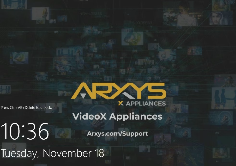
4. Press CTRL+ALT+Delete to unlock the system. Type in the credentials created in the previous step.
5. Once logged in, the system will auto start the VMS installer (if specified) for the integrator to install and configure.
Configuring Network Settings #
The organization network administrator should be able to provide you with the information required to configure the network on the Arxys VideoX V5 Appliance. Generally, the information required is: IP address, subnet mask, gateway, and DNS server. Some networks run the DHCP protocol which will assign all of the above settings automatically. It is recommended that the Arxys VideoX V5 Appliance be configured with a static IP address.
- Click on the start menu, followed by settings
- At the Windows Settings screen click on the “Network & Internet” section
- Click on the Change adapter options link
- The network connections of the system are displayed. From here you can configure a static IP address. For more information see the Windows Help and Support files.
Checking RAID Health #
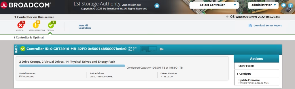
Arxys VideoX V5 Appliances will ship with storage resources pre-configured if the configuration is specified at the time of ordering. Before utilizing the storage resources provided by the Arxys VideoX V5 Appliances, the health of the solid-state disk (SSD), hard disk drives (HDD), and RAID arrays should be verified.
Arxys VideoX V5 V400 Appliances ship with both the Operating System SSDs and Video Storage HDDs respective RAID arrays configured on the same RAID controller. Both arrays are managed and configured through the same utility. An Arxys VideoX V5 V400 Appliance will have a total of 10 Physical Drives; 2x SSDs for the OS and 8x HDDs for video storage.
Video Storage and OS RAID #
Arxys VideoX V5 Appliances ship with the LSI Storage Authority (LSA) utility pre-installed. This utility will be used to verify the status of the HDDs configured for video storage. A shortcut is placed on the desktop named “Video Storage RAID Manager”. It can also be accessed via the start menu. LSA uses the local web browser. Use any local or domain administrative account to log in.
- Log in to the Arxys VideoX V5 Appliance as “administrator” (using the password that was configured during first boot)
- From the desktop or start menu locate the Video Storage RAID Manager shortcut. Double–click the shortcut to start the utility.
- Log in to the utility as “administrator” (using the password that was configured during first boot). Allow the utility to load.
- The status of the raid controller and its volumes are displayed on the top-left corner. The status should display “Optimal.” If the status displays anything other than “Optimal” immediately stop and power off the system. Then verify that:
- Only the drives labeled for use with the system being installed are installed in the system.
- ALL of the drives labeled to use with the system being installed are installed in the system.
- The drives should be installed in the system BEFORE powering on the system.
- Background operations are also displayed in the same menu under the raid controller ID. “Check consistency” and/or “initializing” procedures run on schedules to preemptively correct any errors. If “Check Consistency” or “Initializing” operations are in progress, the video storage array remains in an optimal condition.
- After verifying the optimal status of the video storage array, exit the utility.


Video Management Software #
If specified, Arxys preloads VMS installers for in order to speed up the deployment and setup process. The preloaded VMS installers are located in the folder:
C:\ArxysSupport\VMS
Browse to the VMS folder and double click on the VMS installer application to start the installation process. Follow the onscreen instructions to complete the setup.
Arxys VideoX Enterprise Appliance typically ships with a preconfigured volume to use for video surveillance video called “VideoStorage” and is typically configured in Windows as drive “D:\” The VMS that is being installed should be configured to store video files here.
SQL Server and SQL Express Installation errors #
If you install any version of SQL Server on a Windows Server 2022 device and you may see errors related to installing or starting the Database Engine Services component of SQL Server. Logs will show “SQL Express failed. Error code = -2061893606′”
Additional information can be found here https://learn.microsoft.com/en-us/troubleshoot/sql/database-engine/database-file-operations/troubleshoot-os-4kb-disk-sector-size.
Arxys has internally tested the add ForcedPhysicalSectorSizeInBytes resolution proposed by Microsoft successfully
Additional information regarding this is also available from Milestone here: https://supportcommunity.milestonesys.com/s/article/XProtect-fails-to-install-Windows-11-InstallationAdapterException-error-code-2061893606-troubleshooting?language=en_US
Lastly some VMS installation packages may have custom SQL initialization files that may not work for all environments. For these cases, it is recommended that the appropriate version of SQL be installed prior to installing a VMS. Once SQL is installed and confirmed to be functioning, install the VMS and have it use the existing SQL server.
Milestone VMS Best Practices #
Do not run SMART Client on a recorder.
Do not leave the Management Client open to views that display video feeds. This will cause unnecessary additional load on the recorder.
If more than 300 cameras are on the site, SQL Standard must be used. SQL Express is not recommended for a deployment this large.
Do not exceed 20,000 cameras/day per storage profile. See https://supportcommunity.milestonesys.com/s/article/when-should-I-use-archive-storage?language=en_US
This may require RAID reconfiguration which can be done using LSA.
Configure your maximum recording and archive retention limits so that video is deleted upon a set schedule, and not when the hard disk drive reaches its maximum capacity. For best performance, we recommend to maintain at least 15% of the drive free.
Configure the recording and archive hard drives to have a cluster size (block size) of 64K or higher.
Ensure RAID stripe size is set to 512K or higher.
Disable real-time antivirus scanning; instead choose to scan the system based on a schedule. Consult the XProtect Administrator’s Manual regarding which files/folders and processes to exclude. You can also find more information about anti-virus scanning and XProtect in KB 1004, “Configure anti-virus software on XProtect systems (best practices).”
If your surveillance server storage has one single storage array, do not archive. (See the corresponding KB 3614, “When should I archive?”)
Disable any non-essential Windows tasks and processes that affect the file system. These could include the indexing service and the volume shadow copy service. Also make sure to never use Windows drive compression as it will slow down all write-to-disk operations.
In the RecorderConfig.xml file, the “chunk_files” buffers should be set to 64K
Avigilon VMS Best Practices #
Before starting the ACC setup and installation it is recommended that the built in Windows Server 2022 AntiVirus software (Windows Defender or any additional AntiVirus software loaded by the end user) be temporarily disabled or suspended. During the ACC installation a Storage Configuration will create a storage layout. If Windows Defender is enabled this process will take multiple days to complete. Configure Anti-Virus Settings
Do not leave the ACC client open on the system with a view tab open. This will cause unnecessary additional load on the recorder. https://assets.avigilon.com/documents/avigilon-nvr5-datasheet-en-rev3.pdf (see no local viewing)
If using analytics, verify that the GPU included with the system is operation in TCC mode.
Windows Activation Without Internet Access #
In the event that Internet access is not possible the Windows® Activation procedure can be completed via the use of the Microsoft® Windows® Activation telephone hotline.
- Log into the system as a member of the administrative group.
- From the Start Screen, Type ‘slui 4’ click on the icon to run the wizard.
- Select the nearest location from the drop-down menu and click “Next.”
- Call the phone number displayed and follow the promptings. You will have to provide the “Installation ID” and will receive a “Confirmation ID.”
- Click “Next” and follow the onscreen instructions to continue and complete the activation process.


MegaRAC SP-X BMC #
Arxys VideoX V5 Appliances include MegaRAC SP-X BMC. MegaRAC SP-X BMC offers unparalleled remote management capabilities for Arxys VideoX V5 Appliances. This includes complete out-of-band control, power management, KVM redirection, and virtual media. MegaRAC SP-X BMC delivers seamless performance and reliability, ensuring the stability, safety, and security of your servers at all times.
In order to utilize MegaRAC SP-X BMC you need:
- A configured MegaRAC SP-X BMC
- The management port must be connected to an accessible network
- Modern Web Browser (Edge, Chrome, Firefox)
MegaRAC SP-X DHCP IP #
MegaRAC SP-X is accessed via a web browser by navigating to the baseboard management controller (BMC) IP address and logging in with the appropriate credentials.
If the management port is connected to a DHCP enable network, the MegaRAC SP-X will automatically be assigned an IP address.
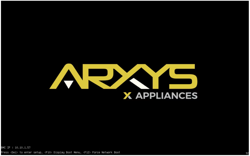
The IP Address will be displayed during the system’s power on self test (POST) screen in the lower left corner.
MegaRAC SP-X Static IP #
When a DHCP network is not availble a static IP will need to be configured.
- Plug in a network cable into management port on the server. See the appliance overview section for more details on the location of the port.
- Power cycle the server (remove AC power, wait 5 seconds, and then plug the AC power back in)
- During POST, enter the BIOS by pressing the “DEL” key.
- Once in the BIOS navigate to the “Server Mgmt” menu using the right arrow key
- Then select the BMC network configuration from the options
- By default the BMC is configured to use DHCP.
- To configure a static IP, select the Configuration Address source and press ENTER.
- From the sub menu select “Static” and press enter
- Use the new options to set:
- the Station IP address (BMC IP Address)
- The subnet mask of the network
- The router or gateway address for the network
- Press escape and navigate to the “Save & Exit” menu.
- Select “Save Changes and Reset” and press <enter>.
- The system will reboot.
- The configured IP address will be displayed on the bottom left corner of the screen.


access MegaRAC SP-X #
- Open a supported web browser
- Navigate to the BMC IP address
- example: https://10.10.1.57
- A privacy error will come up due to the usage of a self signed certificate.
- click advanced and then continue to the site
- click advanced and then continue to the site
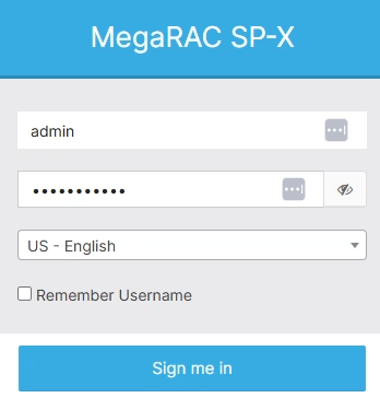
- The MegaRAC SP-X log in screen will be presented
- enter the default user name ‘admin’ (case sensative)
- enter the factory set unique password in the password section (case sensitive)
- Click “sign me in” to continue
- Use the left hand menu to navigate to the various sections
Review Sensor Health #
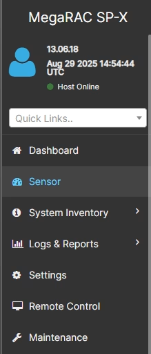
To review the status of the system’s sensors click on the “Sensor” item from the menu on the left.
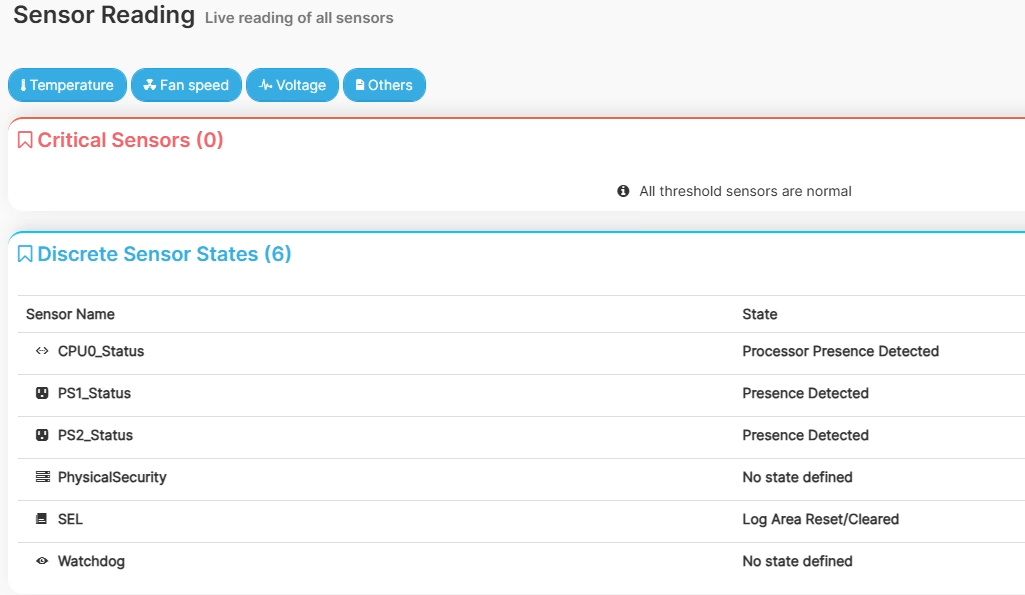
Any sensors that have detected a problem will be highlighted in the “Critical Sensors” section. If the message “All thrshhold sensors are normal” is displayed, all sensors are in a healthy state. Scroll down to see the values and status of the monitored sensors. Some sensors will also have a graph displaying sensor trends.
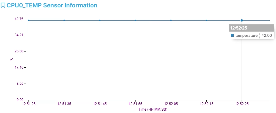
Click on any sensor to display additional details about that specific sensor. For temperature sensors this will start a real time monitor.
Remote Control #
MegaRAC SP-X allows administrators to remote control system by simulating a keyboard, video, mouse (KVM) connetion through the BMC. This will allow for console level control of the sytem remotely.
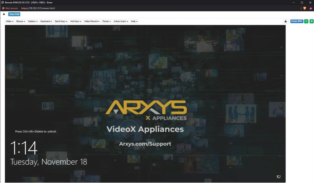
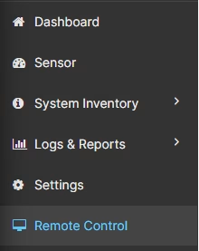
- Click on the “Remote Control” option from the menu
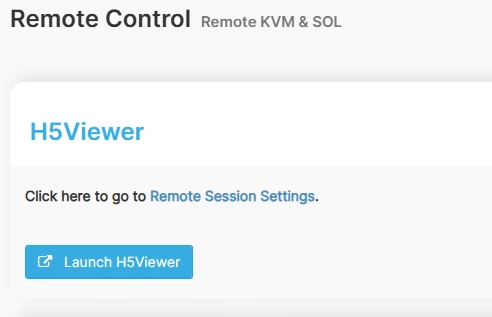
- Click on the “Launch H5Viewer” button
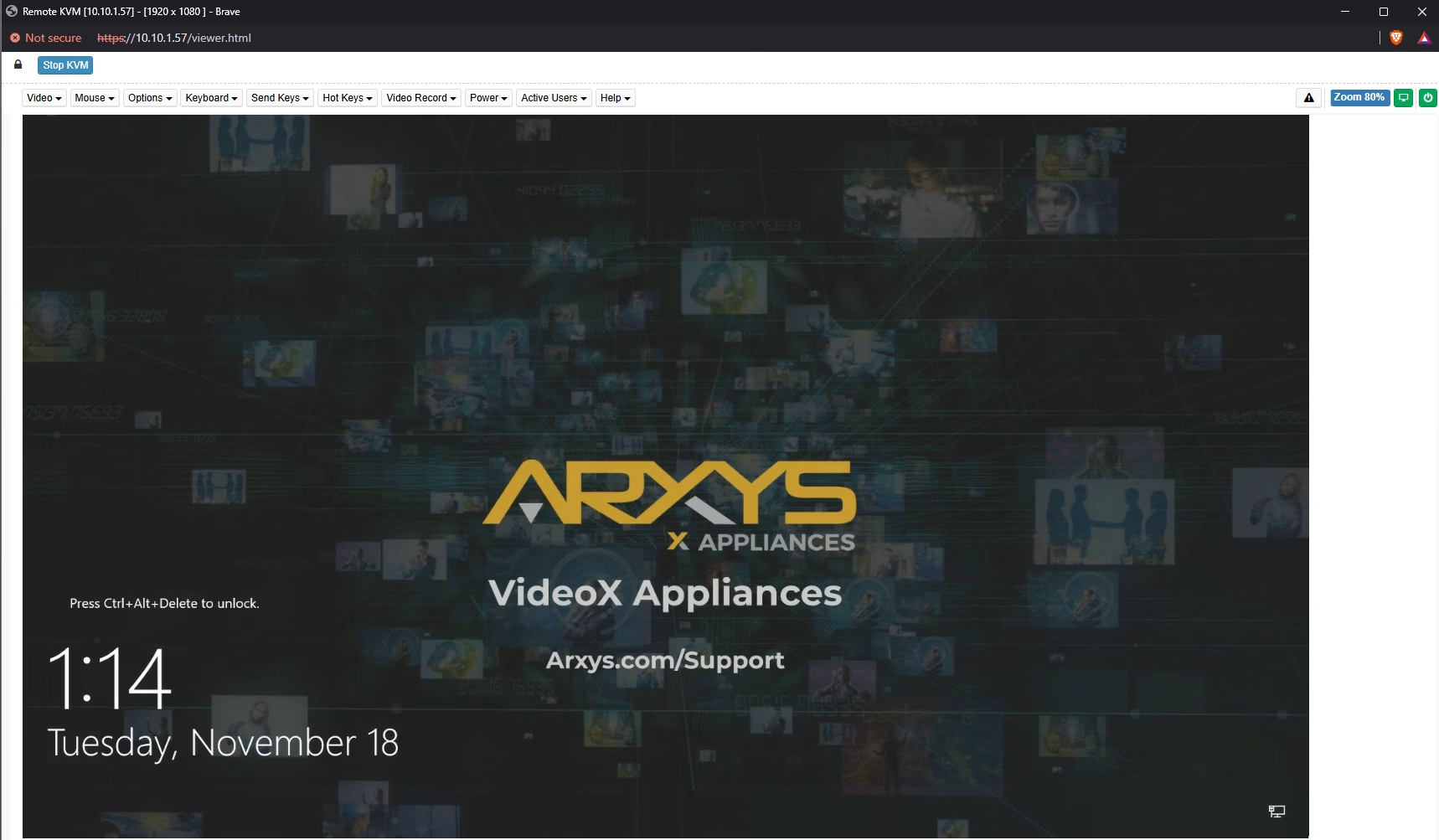
- After a few moment a remote KVM window will appear
- Use the keyboard and mouse to control the system.
Maintenance #
Capturing System Logs #
It may be necessary to capture logs in order to start a support ticket with Arxys. For instructions on how to do this see https://www.arxys.com/docs/capturing-logs-2
Video Storage Drive Replacement #
Video recordings are saved on the hard drives with are protected by RAID. A RAID 6 array is able to continue to operate with two failed drives. Drives should be replaced as soon as possible in order to maintain data resiliency.
If your Arxys VideoX V5 Appliance is still under warranty, contact Arxys to replace the failed hard drive.
- Open the Broadcom LSA utility. A shortcut should be on the desktop.
- Check which HDD has failed and note the slot number shown
- Press the release button on the drive carrier matching the slot number identified. This extends the drive carrier handle
- Use the handle to pull the drive carrier out of the chassis 1-2 inches
- Wait 10 seconds to allow the drive to spin down
- Pull the drive tray out of the chassis
- Swap out the failed HDD with the replacement HDD
- Remove the three (3) fasteners securing the hard drives to the tray from the underside
- Pull the failed hard drive out of the tray
- Align the replacement hard drives with the tray. Ensure that the dimples on the tray match the hard drive
- Reinstall the three (3) fasteners to secure the hard drive to the tray
- Insert the replacement drive tray with the replacement hard drive into the chassis. Make sure to press the drive carrier handle closed until it clicks in place.
- After a few moments the rebuild process will begin automatically. This will be visible in LSA.
- After 20-30 hours (depending on drive capacity and system load) the rebuild process will complete.


Backplane Replacement #
- Shutdown the system
- Remove the AC cords from both power supplies
- Remove all hard drives from the front hot swap bays
- Remove the top cover of the system
- Unplug the two power connectors as well as data cables from the backplane
- Pull the the light blue securing pin towards the inside of the chassis to release the lock. Then swing the opened locking mechanism towards the back of the chassis
- Hold the backplane from both sides and lift it up and out of the chassis.
- To install the replacement backplane, perform steps 4 through 7 in reverse order.
- Replace the system lid
- Reinstall all removed hard drives
- Connect AC cords
- Power on the system


Power Supply Replacement #
If either of the two power supply modules fails, the other module will take the full load and allow the system to continue operation without interruption.
Replacement power supply modules will ship directly from Arxys. The power supply units have a hot-swap capability, meaning you can replace the failed unit without powering down the system.
If your VideoX V4 R8E/R12E is still under warranty, contact Arxys to replace the failed power supply.
Removing a Power Supply Module #
- Identify the failed power supply (Amber LED)
- Unplug the AC power cord from the failed power supply module.
- Orient the handle to pull it straight out
- Depress the release tab on the power supply module.
- Pull the power supply out.


Installing a Power Supply Module #
- Replace the failed hot-swap unit with another identical power supply unit.
- Push the new power supply unit into the power bay until you hear a click.
- Secure the locking tab on the unit.
- Finish by plugging the AC power cord back into the unit.


