
- ArcGIS Data Appliance
- Introduction
- Getting Help
- Default Passwords
- Installation Requirements
- Unpacking the system
- The ArcGIS Data Appliance
- Revealing the Windows Product Key
- Rackmount Installation
- Connecting Cables
- Powering on the ArcGIS Data Appliance for the first time
- Configuring Network Settings
- Checking Collection Health
- Setting up ArcGIS Data Appliance
- Windows Activation Without Internet Access
- IPMI Configuration and Usage

ArcGIS Data Appliance #
Configured with Microsoft® Windows Server 2022 #
COPYRIGHT
No part of this manual may be reproduced, stored in a retrieval system, or transmitted, in any form or by any means, electronic, mechanical, recording, or otherwise, in whole or part, without prior written consent from Arxys.
All rights reserved. Copyright © 2024 Arxys.
TRADEMARKS
All trademarks and copyrights stated, mentioned, referenced or omitted are the property of their respective owners.
DISCLAIMER
This document has been generated and made available using product descriptions and specifications available at the time of publication. The contents of this document and the specifications of the products discussed herein are subject to change without notice. Arxys reserves the right to make any such changes without notice. Arxys does not: (1) guarantee the completeness or accuracy of the information contained in this document; or (2) is responsible for your use of, or reliance on, the information. Arxys shall not be responsible for any losses or damages (including consequential damages) caused by reliance on the information presented herein.
Introduction #
ArcGIS Data Appliance enables you to create, publish, and share map services with colleagues securely behind your firewall. It connects directly into your internal network and comes preloaded with terabytes of global basemaps and reference layers.
ArcGIS Data Appliance is a content solution that consists of hardware and data and is designed to run with ArcGIS Enterprise software.
ArcGIS Data Appliance gives you cartographically rich mapping content and basic tasks you need to start building critical GIS applications right away. Terabytes of rich, ready-to-use world maps such as imagery, street maps, topographic maps, shaded relief, elevations, and more are available.
Serve and store your data and services securely behind your firewall. Because these custom services and data are open and interoperable, people across your organization can use them.
You can publish data immediately to support workflows behind your firewall and share the content across your organization. For specialized analysis and visualization, you can build custom services that you can save and share. You can also integrate other data into the maps on ArcGIS Data Appliance.
Use Restrictions #
The ArcGIS Data Appliance is a specialized Network Attached Storage device. Arxys manufactures the ArcGIS Data Appliance for the exclusive use with Esri products. The ArcGIS Data Appliance is designed to be a read-only device. Except for specific updates provided by Esri the Data Appliance for ArcGIS should never be written to or used as an additional storage device. The ArcGIS Data Appliance ships with a single use appliance license for the Microsoft® Windows Server 2022 operating system. This license precludes the installation of additional software or adding additional roles to the appliance to those that have been preloaded at the factory.
- The ArcGIS Data Appliance can only be used to support Esri products
- The ArcGIS Data Appliance cannot be used in any other role other than that of a NAS supporting an ArcGIS environment
- The end user is not authorized to install additional software on the ArcGIS Data Appliance. This includes system utilities (anti-virus software, remote management, etc.) server applications (web server, ftp, directory services) or backup software.
The violation of any of the above restrictions will require the user to return the system to the factory default configuration before troubleshooting and warranty services can be processed
Getting Help #
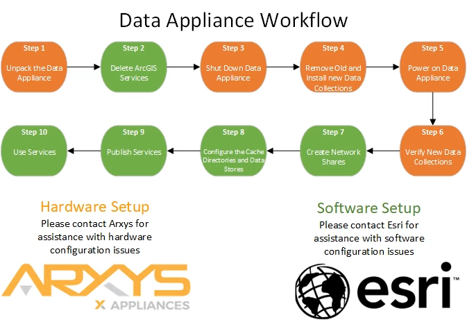
Support for ArcGIS Data Appliance will be provided by both Esri and Arxys technical support teams.
Esri Support #
For questions regarding the configuration and setup of ArcGIS services and usage, contact the following:
United States users—Support will be provided by Esri Technical Support. Please use the following contact options:
Phone: 1-888-377-4575
Fax: 1-909-792-0960
E-mail: support@esri.com
Hours: Monday–Friday, 5:00 a.m.–5:00 p.m. Pacific time (excluding Esri holidays)
International users—Support will be provided by your local Esri distributor.
https://doc.arcgis.com/en/data-appliance/latest/get-started/setup-da.htm
Arxys Support #
For questions and support regarding the ArcGIS Data Appliance hardware, please contact Arxys using the following options:
Web: https://support.arxys.com/
Hours: Monday – Friday, 8:00 a.m.–5:00 p.m. (Pacific time) Holidays Excluded
Please see this section for information on opening a ticket with Arxys: https://www.arxys.com/docs/starting-ticket/
Web page: https://www.arxys.com/company/support
Default Passwords #
Operating System #
The Windows operating system administrator password is configured by the end user during the first boot setup procedure.
The password configured by the end user cannot be reset by Arxys
There is no default or backup account.
BIOS #
There is no factory configured BIOS password. The BIOS can be accessed via local or remote console.
BMC – IPMI – Remote Management #
User Name #
Default IPMI Credentials: The default user is ‘admin’.
Password #
All ArcGIS Data Appliances have a unique BMC password.

ArcGIS Data Appliance will have a label with both the system serial number and unique BMC password on the top right hand of the system.
Arxys HIGHLY recommends that this password also be changed to a unique password known only to system administrators to prevent unauthorized access to the ArcGIS Data Appliance
What is included #
- Esri ArcGIS Data Appliance
- Hard disk drives containing Esri data collection(s); quantities vary
- Rackmount Rail Kit and fasteners
Installation Requirements #
The proper installation of the Esri ArcGIS Data Appliance will require the following hardware and resources:
- Keyboard and mouse.
- Display monitor capable of 1024×768 resolution with a Standard VGA connector
- Gigabit Ethernet connectivity
- Network IP address
- Available space in a computer equipment rack 1U, 2U, or 4U depending on the ArcGIS Data Appliance model.
- Available ports in an uninterruptable power supply (UPS).
Unpacking the system #
Esri ArcGIS Data Appliances are shipped with all hard drives installed.
- Open the shipping box
- Remove the rail kit box and set it aside for later use
- Remove the system accessory box and set it aside for later use or storage
- Remove both the front and rear foam and set it aside for later storage
- Carefully remove the system from the shipping box. It is recommended that two people remove the system together. The system will be front heavy. Set the system on a clear working surface
- Remove the Esri Data Appliance from the shipping bag and place it on a clean flat surface.
The ArcGIS Data Appliance #
Front View #

| 1 | Front panel buttons and indicators |
| 2 | Reset buttons |
| 3 | 2x USB 3.2 Gen 1 Ports |
| 4 | 24x Front data collection drive bays |
Front Panel Buttons and Indicators #
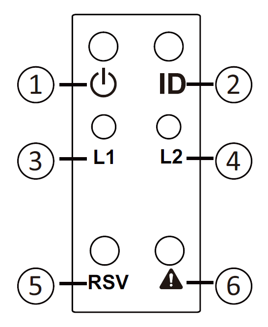
| 1 | Power Button with LED | Press the button to power on the system. The LED will be solid green when the system is powered on. |
| 2 | ID Button | Press the button to activate system identification |
| 3 | LAN 1 LED | Solid green for 10Gb/s connectivity. Flashing green for 10Gb/s activity. Solid amber for 1Gb/s connectivity. Flashing amber for 1Gb/s activity |
| 4 | LAN 2 LED | Solid green for 10Gb/s connectivity. Flashing green for 10Gb/s activity. Solid amber for 1Gb/s connectivity. Flashing amber for 1Gb/s activity |
| 5 | Reserved Button | Not utilized |
| 6 | System Status LED | Solid green for normal operations. Solid amber for system fan or temperature alarm. Flashing amber for power supply failure |
Rear View #

| 1 | PCIe expansion slots |
| 2 | ID Button with LED |
| 3 | IPMI remote management port for out of band management |
| 4 | USB 3.2 ports |
| 5 | Two (2) 10 Gb/s Ethernet ports. |
| 6 | Two (2) 1 Gb/s Ethernet ports. |
| 7 | RJ45 Type Serial Port (Do not connect an Ethernet cable here) |
| 8 | VGA connector |
| 9 | OS drives |
| 10 | 12x Rear data collection drive bays |
Dimensions #
Width x Depth x Height
17.7 x 24.6 x 4.6 (4U) inches
450 x 625 x 117 millimeters
Power Usage #
Compatible AC Input Ranges: 100-127V~/ 12A, 50-60Hz and 200-240V~/ 10A, 50-60Hz
The power usage listed below were measured under an typical Data Appliance use case using a 120 VAC power source. Actual power usage will vary depending on many factors.
| ArcGIS Data Appliance 2024 / 2025 / 2026 4U w/ 24x HDDs – 120VAC | Current (Amps) | Power (Watts) |
| Idle | TBD | TBD |
| High Load | 2.4 | 285 |
| Power On (Peak) | TBD | TBD |
| Power Supply Maximum | 12 | 1440 |
| ArcGIS Data Appliance 2024 / 2025 / 2026 4U w/ 24x HDDs – 240VAC | Current (Amps) | Power (Watts) |
| Idle | TBD | TBD |
| High Load | 1.2 | 290 |
| Power On (Peak) | TBD | TBD |
| Power Supply Maximum | 10 | 1600* |
Revealing the Windows Product Key #

The product key is found on the Microsoft® Certificate of Authenticity (COA) label located on the front left corner of the appliance. Similar to the removable material commonly found on lottery tickets or prize vouchers, this concealment panel is designed to protect the consumer’s product key from being obtained and used by unauthorized individuals. Carefully scratch off the concealment coating with a fingernail or coin to reveal the entire product key
Rackmount Installation #
- Install the largest and heaviest items on the bottom of your rackmount rack.
- Ensure that the leveling jacks on the bottom of the rack are fully extended to the floor with the full weight of the rack resting on them and not the casters.
- In single rack installation, stabilizers should be attached to the rack. In multiple rack installations, the racks should be coupled together.
- Always make sure the rack is stable before extending a component from the rack.
- You should extend only one component at a time – extending two or more simultaneously may cause the rack to become unstable.
- Determine the placement of each component in the rack before you install the rails.
- Use a regulating uninterruptible power supply (UPS) to protect the server from power surges, voltage spikes and to keep your system operating in case of a power failure.
- Always keep the rack’s front door and all panels and components on the servers closed when not servicing to maintain proper cooling.
- Equipment should be mounted into a rack so that the amount of airflow required for safe operation is not compromised.
- Consideration should be given to the connection of the equipment to the power supply circuitry and the effect that any possible overloading of circuits might have on overcurrent protection and power supply wiring. Appropriate consideration of equipment nameplate ratings should be used when addressing this concern.
Removing the hard drives from the system #
The hard disk drives shipped in the system can be temporarily removed from the system in order to reduce the weight of the system. The drives are locked in. Use the included tool in the accessory bag to unlock the drives and carefully remove them from the system.

- Press the release button. If the button does not release the lever, the drive needs to be unlocked using the included tool.
- Extend the locking lever.
- Pull the locking lever out and away from the system
- Slide the hard disk drive and drive tray out and set aside for reinstallation
Rail Kit Installation #
This section provides information on installing the ArcGIS Data Appliance 4U into a server rack with the quick-release rails provided. There are a variety of rack units on the market, which may mean the assembly procedure will differ slightly. You should also refer to the installation instructions that came with the rack unit you are using.
NOTE: This rail will fit a rack between 26.5″ and 36.4″ deep.
The ArcGIS Data Appliance 2024 / 2025 / 2026 4U should be installed into the rack without hard disk drives installed.
There are two rack rail assemblies in the rack mounting kit. Each assembly consists of two sections: an inner fixed chassis rail that secures directly to the server chassis and an outer fixed rack rail that secures directly to the rack itself. Two pairs of short brackets to be used on the front side of the outer rails are also included.
Inner Rails #

- Unbox the rail kit
- Pull the inner rail out of the outer and middle rail until it is fully extended.
- Pull forward on the locking mechanism to release the inner rail and pull the inner rail out of the outer rail

- Press the inner rail tightly against the chassis and slide the inner rail backwards until it clicks into the locked position.
- Secure the inner rails to the chassis with the one of the short pan head fasteners provided on each side.
- Repeat steps 1-5 for the other side.

Outer and Middle Rails #

- Press the locking tab and push the middle rail back into the outer rail.
- Hang the hooks of the rails on the rack holes and secure with screws
- Repeat step 2 for the rear of the outer rail. Extend the rail as necessary.
- The rails MUST be secure with fasteners. Use the larger fasteners provided if appropriate for the rack be being used to secure the outer rail to the rack.
- Verify that the rail is level and not bowed in either direction
- Repeats steps 1 through 5 for the other side.


Installing the Chassis in the rack #

- Confirm that the inner rails are properly installed on the chassis.
- Confirm that the outer rails are correctly installed on the rack.
- Pull the middle rail out from the front of the outer rail and make sure that the ball-bearing shuttle is at the front locking position of the middle rail.
- Align the chassis inner rails with the front of the middle rails.
- Slide the inner rails on the chassis into the middle rails, keeping the pressure even on both sides, until the locking tab of the inner rail clicks into the front of the middle rail, locking the chassis into the fully extended position.
- Depress the locking tabs of both sides at the same time and push the chassis all the way into the rear of the rack.
- The chassis MUST be secured to the rack with fasteners. Use the appropriate fasteners provided recommend by the rack manufacturer.
Reinstalling the hard drives into the system #
Before proceeding, verify that the hard drives are labeled with the same serial number listed on the Esri ArcGIS Data Appliance which is located on the chassis.
- Press the release button on the drive tray to extend the locking lever.
- Carefully align the hard drive and hard drive tray and slide them into the chassis making sure the drive is pushed completely forward.
- Close the locking lever to secure the drive.
- Use the locking tool to relock the hard drive into the system.

Connecting Cables #
Make the following connections:
- Connect the Esri ArcGIS Data Appliance to either a KVM or a dedicated keyboard/mouse and monitor. The keyboard and mouse can be connected to either USB ports. It is recommended that a monitor be connected to the mini display port in order to maintain the remote KVM functionality in IPMI.
- Connect the Esri ArcGIS Data Appliance to your network by plugging an Ethernet cable into one of the Ethernet ports. Verify that the appropriate switch port is utilized.
- For out of band management connect an Ethernet cable to the IPMI remote management port. This is high recommended.
- Connect a power cable to each power supply. Verify that the power cable is connected directly to a UPS or through an appropriate power distribution unit.
Powering on the ArcGIS Data Appliance for the first time #
To power on ArcGIS Data Appliance press the power button located on the left side of the system.
ArcGIS Data Appliance is delivered with the Microsoft® Windows® Server 2022 operating system. The Windows operating system requires an initial configuration when used for the first time.
When ArcGIS Data Appliance is first powered the Microsoft® Windows® Server 2022 will begin booting. Please do not interrupt or power off ArcGIS Data Appliance during this process. ArcGIS Data Appliance may automatically reboot as the final configuration is applied to the system.
ArcGIS Data Appliance OS Setup #
After the system reboots the Windows® Server 2022 operating system will load. Follow the onscreen instructions to continue.

At the “Hi there” screen select the correct home country/region, the preferred app language, and the keyboard layout to use. Once correctly selecting the options needed click the Next button to continue

At the “It’s time to enter the product key” screen enter the product key that is on the Microsoft® COA label attached to the system. The COA label is attached on the top front left corner of the system. It may be required to scratch off some of the protective/privacy silver coating to reveal the entire product key. Click on the “next” button to continue.
See section Revealing the Windows Product Key. If the product is not available (remote install) click the ‘Do this later’ link to continue. Note that Windows will not activate until the product key is entered.
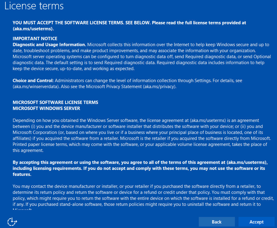
At the “License terms” screen review and accept the Microsoft® Windows® Server 2022 license agreement.

At the “Customize settings” screen, set a password for the local administrator account. The password should:
- Have a minimum length of 7 characters.
- Meet the complexity requirements. See https://technet.microsoft.com/en-ca/library/cc956977.aspx for details
- Do not lose this password. This password will be needed to log into the system in order to continue the configuration of the server.
Type in the password twice as indicated on the screen and click on the “finish” button to continue. Arxys Support cannot reset this password and there is no default password configured.

Press CTRL+ALT+Delete to unlock the system. Type in the credential created in the previous step.
After a few moments the Windows desktop will load.
Configuring Network Settings #
Your organization’s network administrator should be able to provide you with the information required to configure the network on ArcGIS Data Appliance. Generally, the information required is: IP address, subnet mask, gateway, and DNS server. Some networks run the DHCP protocol which will assign all of the above settings automatically. It is recommended that ArcGIS Data Appliance be configured with a static IP address.
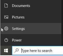
- Click on the start menu, followed by settings
- At the Windows Settings screen click on the “Network & Internet” section
- Click on the Change adapter options link
- The network connections of the system are displayed. From here you can configure a static IP address. For more information see the Windows Help and Support files.
Checking Collection Health #
ArcGIS Data Appliance will ship with storage resources pre-configured if the configuration is specified at the time of ordering. Before utilizing the storage resources provided by the ArcGIS Data Appliance, the health of the solid-state disk (SSD), hard disk drives (HDD), and RAID arrays should be verified.
ArcGIS Data Appliance ships with the LSI Storage Authority (LSA) utility pre-installed. This utility will be used to verify the status of the HDDs configured with imagery collections. LSA uses the local web browser. Use any local or domain administrative account to log in.
- Log in to the ArcGIS Data Appliance as “administrator” (using the password that was configured during first boot)
- From the desktop or start menu locate the LSI Storage Authority (LSA) shortcut. Double–click the shortcut to start the utility. If the shortcut is not on the desktop, use the search bar in the start menu to locate it.
- Log in to the utility as “administrator” (using the password that was configured during first boot). Allow the utility to load.
- The status of the raid controller and its volumes are displayed on the top-left corner. The status should display “Optimal.” If the status displays anything other than “Optimal” immediately stop and power off the system. Then verify that:
- Only the drives labeled for use with the system being installed are installed in the system.
- ALL of the drives labeled to use with the system being installed are installed in the system.
- The drives should be installed in the system BEFORE powering on the system.
- Background operations are also displayed in the same menu under the raid controller ID. “Check consistency” and/or “initializing” procedures run on schedules to preemptively correct any errors. If “Check Consistency” or “Initializing” operations are in progress, the video storage array remains in an optimal condition.
- After verifying the optimal status of the video storage array, exit the utility.


Setting up ArcGIS Data Appliance #
Documentation on setting up the ArcGIS Data Appliance is maintained by Esri. It is available here: https://doc.arcgis.com/en/data-appliance/latest/get-started/setup-da.htm
Windows Activation Without Internet Access #
In the event that Internet access is not possible the Windows® Activation procedure can be completed via the use of the Microsoft® Windows® Activation telephone hotline.
- Log into the system as a member of the administrative group.
- From the Start Screen, Type ‘slui 4’ click on the icon to run the wizard.
- Select the nearest location from the drop-down menu and click “Next.”
- Call the phone number displayed and follow the promptings. You will have to provide the “Installation ID” and will receive a “Confirmation ID.”
- Click “Next” and follow the onscreen instructions to continue and complete the activation process.


IPMI Configuration and Usage #
Arxys VideoX Enterprise Appliance include Intelligent Platform Management Interface (IPMI) 2.0 compliant interface that allows you to monitor, control, and manage a remote server from the locally or remotely via the local network. With IPMI you can completely and efficiently monitor your server in real time. IPMI includes remote KVM (keyboard, video, mouse) support.
In order to utilize IPMI you need:
- A configured BMC
- Available network port (RJ-45)
- Modern Web Browser (Edge, Chrome, Firefox
Configuring IPMI Network in the BIOS #

- Plug in a network cable into IPMI port on the server. See the appliance overview section for more details on the location of the port.
- Power cycle the server (remove AC power, wait 5 seconds, and then plug the AC power back in)
- During POST, enter the BIOS by pressing key.
- Once in the BIOS navigate to the “Server Mgmt” menu using the right arrow key
- Then select the BMC Network configuration from the options
- By default, IPMI will grab an IP address from DHCP. If the IP assigned is acceptable note the IP and skip to REMOTELY ACCESSING THE SERVER
- To change to a static IP; select the Configuration Address source and press ENTER.
- From the sub menu select Static and press enter
- Use the new options to set:
- The IP address for IPMI
- The subnetmask of the network
- The router or gateway address for the network
Press escape and navigate to the “Exit” menu. Select “Save Changes and Reset” and press <enter>. The system will reboot.


Remotely accessing the System #
- Utilize a web browser to browse to the IP address set listed in the IPMI section of the BIOS making sure to start with https://
- Example: https://192.168.1.100
- Example: https://192.168.1.100
- A log in prompt will be presented.
- IPMI is now configured and accessible.
- The default user is ‘admin’ the password will be unique for each system. The password is located on a silver label attached to the top right-hand side of the system near the serial number. See https://www.arxys.com/docs/videox-v3-administrator-manual/arxys-videox-enterprise-ipmi-password

Starting A Remote KVM Session #
In troubleshooting or remote managing the system it may be required to establish a remote KVM sessions with the system. A remote KVM sessions will simulate having a keyboard, video display, and mouse connected to the system. This will allow you enter the BIOS of the system and other pre-OS sections of the system. Not that post operating system video will ONLY be displayed if there is a display connected to the VGA connector of the system.
- Establish a web GUI session using https://IP_address
- Log in
- Click the Launch H5Viewer button to start the session. A new browser window will be opened. Note some browsers/settings may block this popup. Make sure to enable all popups from this site. For information on how to do this consult your web browsers documentation
- A remote KVM session is now established. Use the Send Keys drop down menu to send a CTRL+ALT+DEL key stroke to the system to unlock.


Data Set Upgrade #
Before performing a data collection upgrade make sure to review and understand all the steps required and outlined by Esri at: https://doc.arcgis.com/en/data-appliance/latest/get-started/existing-users-da.htm
While a failed hard drive can be replaced while the system is powered on, a data collection upgrade must be performed while the system is powered off. Failure to do so may cause data loss. When removing a data collection, make sure to remove ALL of the hard drives that make up that collection. The replacement data collection may be configured with more or less hard drives. Use the labels on the hard drives drives to confirm that all hard disk drives are present.
The hard disk drives shipped in the system can be temporarily removed from the system in order to reduce the weight of the system. The drives are locked in. Use the included tool in the accessory bag to unlock the drives and carefully remove them from the system.
Removing the old data collection #
- After completing steps 1 through 3 of the Esri documentation listed here: https://doc.arcgis.com/en/data-appliance/latest/get-started/existing-users-da.htm, Shutdown the system.
- With the system power off remove any bezel (if attached) from the system in order to expose the hard drives
- Press the release button. If the button does not release the lever, the drive needs to be unlocked using the included tool.
- Extend the locking lever.
- Pull the locking lever out and away from the system
- Slide the hard disk drive and drive tray out and inspect the label on the hard disk drive. If it is part of the data collection being removed, remove the drive. If it is part of the data collection being kept, reinstall
- Repeat steps 1 through 4 for the remainder of the drives.
- Confirm that ALL the drives from the old collection were removed from the system. Data collection drives will be labeled with how many drives there are in the collection, For example: Drive 1 of 6. This would imply that this data collection is on 6 drives. Make sure to remove ALL 6 drives from the system.
Installing the new data collection #
- After completing steps 1 through 3 of the Esri documentation listed here: https://doc.arcgis.com/en/data-appliance/latest/get-started/existing-users-da.htm, Shutdown the system.
- With the system power off remove any bezel (if attached) from the system in order to expose the hard drives
- It is possible that the new collection may consist of less hard disk drives than the previous collection.
Before proceeding, verify that the hard drives are labeled with the same serial number listed on the Esri ArcGIS Data Appliance which is located on the chassis.
- Press the release button on the drive tray to extend the locking lever.
- Carefully align the hard drive and hard drive tray and slide them into the chassis making sure the drive is pushed completely forward.
- Close the locking lever to secure the drive.
- Use the locking tool to relock the hard drive into the system.
- Repeat steps 1 through 4 for all hard disk drives in the data collection being installed. It is imperative that ALL hard disk drives from the collection are installed. Reference the labels on the hard disk drives to make sure that all drives are installed.


