- Introduction
- Getting Help
- VideoX Enterprise Appliance Windows Password
- VideoX Enterprise Appliance BMC/ IPMI Password
- VideoX Enterprise Appliance Overview
- VideoX V4 R60E NVR Front View
- VideoX V4 R60E NVR Front Panel Buttons and LEDs
- VideoX V4 R60E NVR - Rear View and Connectors
- VideoX V4 R60E NVR Dimensions
- VideoX V4 R60E Storage Expansion Front View LEDs
- VideoX V4 R60E Storage Expansion - Rear View LEDs
- VideoX V4 R60E Storage Expansion - Rear Connectors
- VideoX V4 R60E Storage Expansion Dimensions
- Power Usage
- System Contents
- Installation Planning
- Rackmount Installation Guidelines
- Installation Requirements
- Unpacking the VideoX Enterprise Appliance
- Arxys VideoX Enterprise Appliance R60E NVR Rail installation.
- Attaching the inner rail to the system
- Installing the outer rails in the rack
- Installing the system into the rack
- Arxys VideoX Enterprise Appliance R60E Storage Expansion Rail installation
- Step 7
- VideoX V4 R60E NVR to VideoX V4 R60E Storage Expansion Cabling Diagram
- Connecting Cables and Powering On
- Revealing the Windows Product Key
- Log Into Windows For The First Time
- Checking RAID Health
- Video Management Software
- Windows Activation Without Internet Access
- IPMI Configuration and Usage
- Maintenance
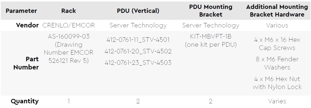
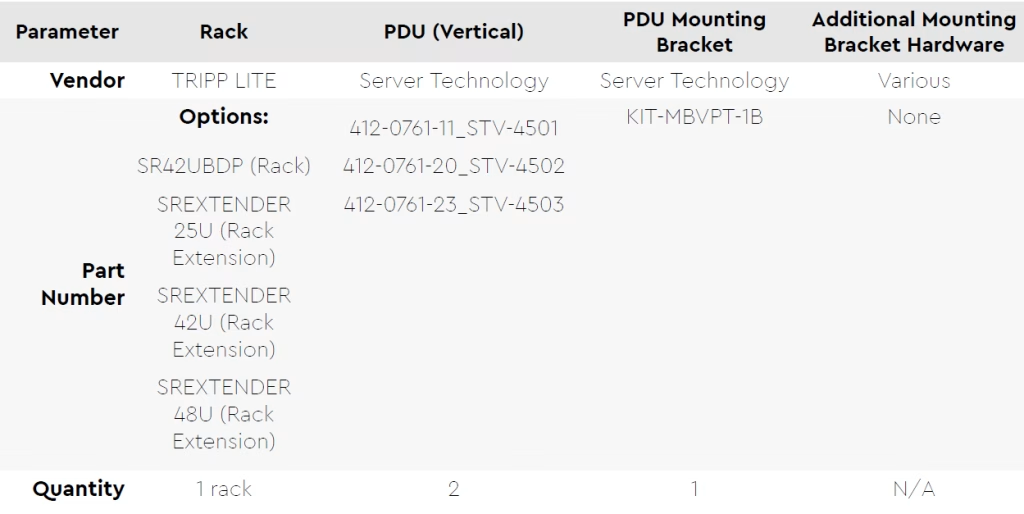
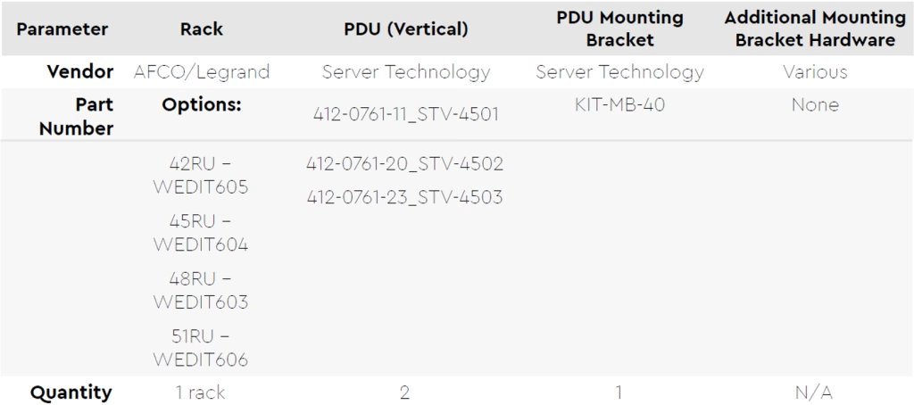
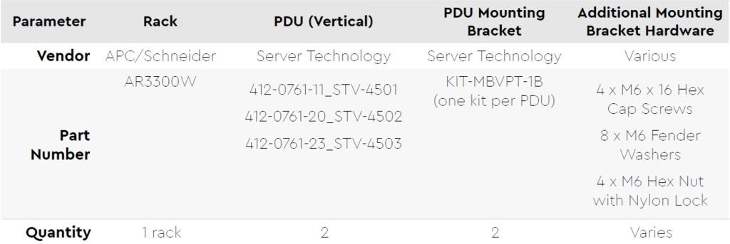
- Compatible Hardware
COPYRIGHT
No part of this manual may be reproduced, stored in a retrieval system, or transmitted, in any form or by any means, electronic, mechanical, recording, or otherwise, in whole or part, without prior written consent from Arxys.
All rights reserved. Copyright © 2024 Arxys.
TRADEMARKS
All trademarks and copyrights stated, mentioned, referenced or omitted are the property of their respective owners.
DISCLAIMER
This document has been generated and made available using product descriptions and specifications available at the time of publication. The contents of this document and the specifications of the products discussed herein are subject to change without notice. Arxys reserves the right to make any such changes without notice. Arxys does not: (1) guarantee the completeness or accuracy of the information contained in this document; or (2) is responsible for your use of, or reliance on, the information. Arxys shall not be responsible for any losses or damages (including consequential damages) caused by reliance on the information presented herein.
Introduction #
The Arxys VideoX V4 Appliances – Enterprise are Network Video Recorders (NVRs) preloaded with Microsoft Windows Server operating system and are configured for ease of use by video surveillance integrators. VideoX V4 Appliances – Enterprise products have been tested with various VMS solutions and offer unparalleled value and performance. VideoX V4 Appliances – Enterprise products may ship with a specific VMS installer for the convenience of the video surveillance integrator. Please contact sales@arxys.com for more information regarding on VideoX V4 Appliances – Enterprise and a specific VMS solution.
The Arxys VideoX V4 Appliance – Enterprise R60E product is 1U NVR with one 4U storage expansion chassis (total 5U) that can support up to 500 cameras and up to 3,000 Mbit/s. The Arxys VideoX V4 Appliance – Enterprise R60E is configured with various storage capacities ranging from 1,080TB to 1,440TB.
The Arxys VideoX V4 Appliance – Enterprise is not an all-in-one video surveillance system. Viewing clients and other infrastructure roles should NOT be installed or run on the system. Arxys VideoX V4 Appliance – Enterprise R60E must be used in conjunction with a dedicated management server and database server.
The Arxys VideoX V4 Appliance – Enterprise R60E requires a power source capable pf providing at least 200 VAC and up to 240VAC. Power sources between 110VAC and 125VAC will not work.
Getting Help #
For questions and support regarding the Arxys VideoX Enterprise Appliance hardware, please contact Arxys using the following options:
Web: https://support.arxys.com/
Hours: Monday – Friday, 8:00 a.m.–5:00 p.m. (Pacific time) Holidays Excluded
Web page: https://www.arxys.com/company/support
The primary method to receive help and support for Arxys VideoX Appliances is through the online ticket system.
Opening A Ticket #
Please see this section for information on opening a ticket with Arxys: https://www.arxys.com/docs/starting-ticket/
VideoX Enterprise Appliance Windows Password #
The Windows operating system administrator password is configured by the end user during the first boot setup procedure.
The password configured by the end user cannot be reset by Arxys.
VideoX Enterprise Appliance BMC/ IPMI Password #
Default IPMI Credentials: The default user is ‘admin’.
Important Notice for BMC “admin” Login Credentials
Arxys has implemented a new security feature enhancement on all VideoX V4 products. The change of the previously default ASMB10-iKVM BMC password to a unique password for the “admin” user will provide greater ASMB10-iKVM BMC security.
To access the web interface; open a web browser and navigate to https://N.N.N.N, where N.N.N.N is the IP address assigned to the management port by a DHCP server on your network. The IP address is displayed on the bottom right corner during boot up.

All VideoX V4 products will have a label with both the system serial number and unique ASMB10-iKVM BMC password on the top right hand of the system.
Arxys HIGHLY recommends that this password also be changed to a unique password known only to system administrators to prevent unauthorized access to the VideoX V4 ASMB10-iKVM BMC module.
For more information on accessing the IPMI/BMC functionality of the VideoX V4 products please go to https://www.arxys.com/company/support/ for additional documentation.
VideoX Enterprise Appliance Overview #
VideoX V4 R60E NVR Front View #

| Diagram ID | Description |
| 1 | Front USB 3.2 Ports |
| 2 | Front Panel LEDs and Buttons |
| 3 | Hot swap solid state drive bays for the system operation system. |
VideoX V4 R60E NVR Front Panel Buttons and LEDs #


If the hard drive LEDs are solid blue with blinking red, without any of the drives having a solid red LED, the system is performing a consistency check or patrol read on the hard drives. This is normal and can be confirmed in LSA. Try not to interrupt the system by restarting it as this will cause the consistency check to restart.
VideoX V4 R60E NVR – Rear View and Connectors #

1 – Mini DisplayPort
Display connector to be used for initial setup and deployment.
2 – USB Ports
For keyboard and mouse use. Can be used for ocasional removable media, should NOT be used for storage expansion.
3 – Out of band management port for Intelligent Platform Management Interface (IPMI)
Dedicated out of band management RJ45 port
4- One gigabyte Ethernet Port
Accepts Ethernet connections from one network at speeds up to 1 gigabits.
5 – Two (2) 10 gigabit Ethernet ports
Accepts Ethernet connections from two networks at speeds up to 10 gigabits. Backward compatible with 1 gigabit switch ports
6 – Two Redundant Power Supplies
Auto ranging for 110-240 VAC. 1+1 redundant hot swap configuration
7 – Storage Expansion RAID controller
Virtualizes drives into drive groups with additional data protection. RAID levels 1, 5, 6, and 60 are recommended. Connect the Storage Expansion to the NVR through these ports.
Connect a SAS cable between RAID controller port A6 to the the A6 port on the Storage Expansion. Connect a SAS cable between RAID controller port B1 to the the B1 port on the Storage Expansion.
VideoX V4 R60E NVR Dimensions #
Width x Depth x Height
17.25 x 28 x 1.75 (1U) inches
438 x 710 x 43.5 millimeters
VideoX V4 R60E Storage Expansion Front View LEDs #
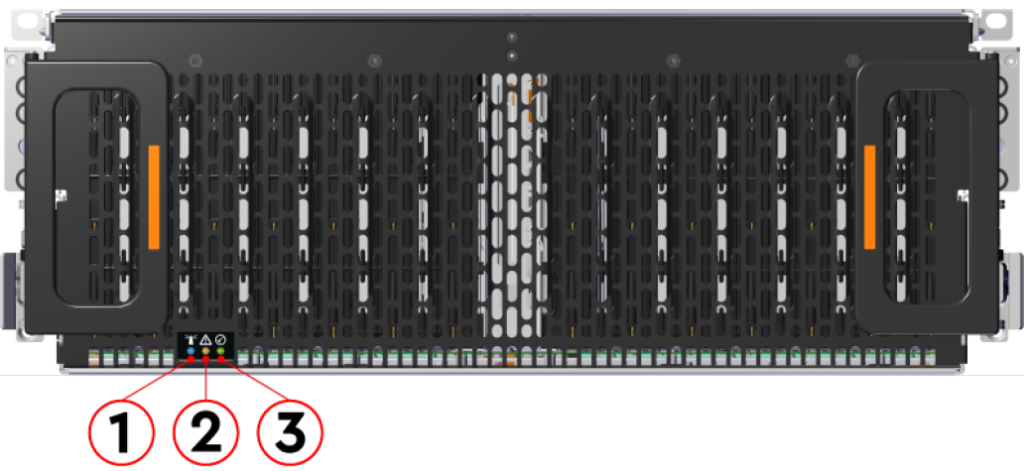
| LED Number | Function | Color | Description |
| 1 | Identify | Blue | Normally off. Blinks at 1Hz when identification has been activated on any component |
| 2 | Fault | Amber | Normally off. Blinks at 1Hz when an enclosure fault has been detected |
| 3 | Power | Green | Normally on. On when system is operational and powered up. |
If the hard drive LEDs are solid blue with blinking red, without any of the drives having a solid red LED, the system is performing a consistency check or patrol read on the hard drives. This is normal and can be confirmed in LSA. Try not to interrupt the system by restarting it as this will cause the consistency check to restart.
VideoX V4 R60E Storage Expansion – Rear View LEDs #
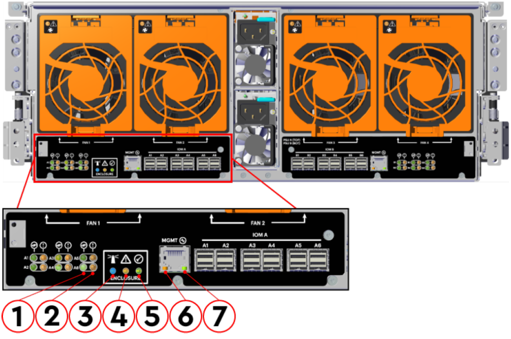
1 – SAS Link Status
Identifies that current status of the SAS port. Normally solid green when a SAS connection is established. Off when a SAS connection is not present.
2 – SAS Fault Status
Normally off for healthy connections. Blinks amber at 1Hz when a SAS connection fault is detected.
3 – Identifications
Normally off. Blinks at 1Hz when identification has been activated on any component
4- Fault
Normally off. Blinks at 1Hz when an enclosure fault has been detected
5 – Power
Normally on. On when system is operational and powered up.
6 – Ethernet Connector Speed
No LED = 10Mbps. Solid Green = 100 Mb/s. Solid Amber = 1Gbps.
7 – Ethernet Connectors Link / Activity
Off = No connection. Solid = Connected. Blink = Activity.
VideoX V4 R60E Storage Expansion – Rear Connectors #
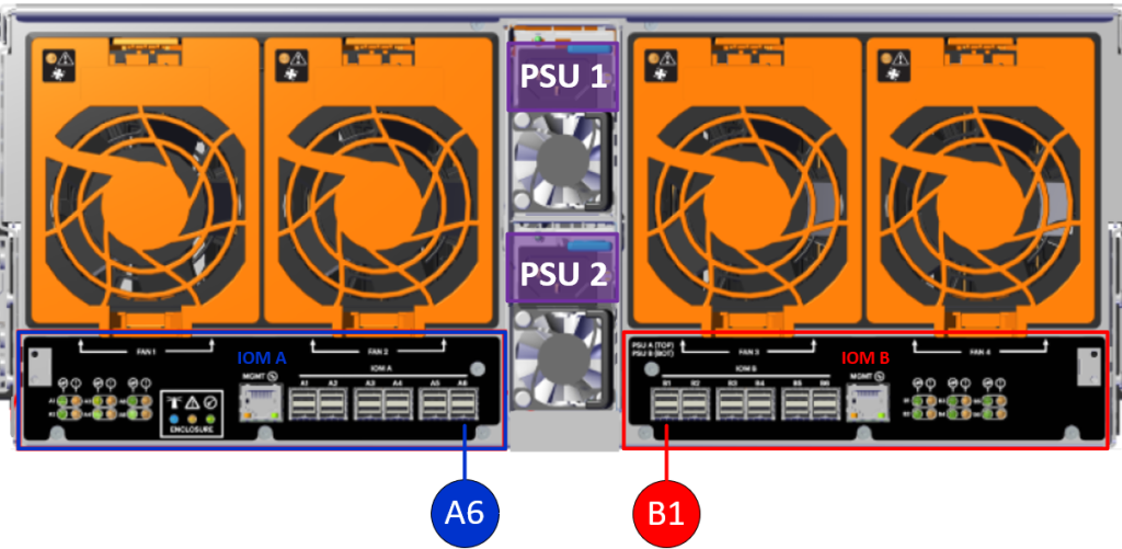
The VideoX V4 R60E Storage Expansion has two Input/Output Modules (IOM). They are designated as IOM A and IOM B.
- Connect a SAS cable between IOM A port A6 and the NVR RAID controller port A6
- On the JBOD side the blue pull tab will towards the top
- On the JBOD side the blue pull tab will towards the top
- Connect a SAS cable between IOM B port B1 and the NVR RAID controller port B1
- On the JBOD side the blue pull tab will towards the top
VideoX V4 R60E Storage Expansion Dimensions #
Width x Depth x Height
17.67 x 35.04 x 6.89 (4U) inches
447 x 890 x 175 millimeters
Length with cable management arms 712mm / 28.03in
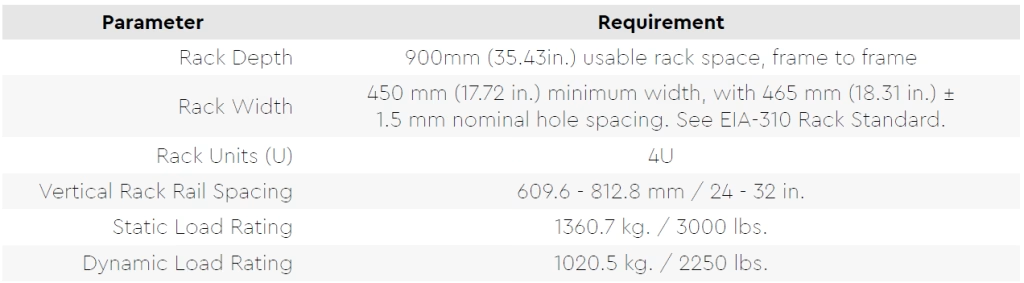
Required Rack Width = 450mm (17.72in) minimum width with 465mm (18.31) 1.5 mm nominal hole spacing. EIA-310 Rack Standard
Required Rack Depth = 900mm (35.43in) usable rack space, frame to frame.
Power Usage #
The power usage listed below were measured under an typical NVR use case using a 208 VAC power source. Actual power usage will vary depending on many factors.
| R60E V4 Storage Expansion – 208VAC | Current (Amps) | Power (Watts) |
| Idle | TBD | TBD |
| High Load | 4.8 | 1000 |
| Power On (Peak) | TBD | TBD |
| Power Supply Maximum | 6 | 1250 |
System Contents #
The R60E Storage Expansion is shipped under an outer sleeve. The R60E NVR is shipped on top for the R60E Storage Expansion. The R60E NVR is shipped in one box. R60E Storage Expansion is shipped in multiple boxes under the protective sleeve.
Arxys VideoX Enterprise Appliance R60E NVR
The top box (box1) will include:
- Arxys VideoX Enterprise Appliance R60E NVR (1U)
- One set of adjustable sliding rails w/ mounting kit
- Mini DisplayPort to VGA Adapter
- Documentation; Quickstart Guide, BMC Password
Arxys VideoX Enterprise Appliance R60E Storage Expansion
Under the protective sleeve the following will be included:
- Accessory tray includes:
- Alignment Brackets Box
- 2 Rack Latch Brackets (1 left, 1 right)
- Screws & Nuts
- 10x M5 cagenuts
- 30x M5 x 12, T15 Torx screws
- 2x M5 x 12 Philips panhead screws (for cover retention)
- 16x custom round washers
- 4x Custom Low-Profile M4 Screws (packaged with the rail kit)
- Cables
- 2x C13 to C14 power cables (3m)
- 2x MiniSAS HD cables (3m)
- Bracket Box
- 2x top cover alignment brackets
- Rails Box
- 2x sets of rails (each including 1 inner rail and 1 outer rails
- Cross-bar
- CMA Arms Box
- 2x CMA arms (1 upper and 1 lower)
- 2x CMA arms (1 upper and 1 lower)
- Alignment Brackets Box
- VideoX Enterprise Appliance R60E Storage Expansion chassis box which includes the main chassis
- Three boxes of HDD assemblies. 20x HDDs will be in each box
If you find that you are missing any of the above items, please contact Arxys at https://support.arxys.com
Installation Planning #
Before You Start #
Arxys recommends that all VideoX V4 R60E NVRs be used in conjunction with an uninterruptable power supply (UPS) in order to protect the hardware.
A UPS system in an integral part of any enterprise deployment and offers protect from power issues such as; unclean power, overvoltage, undervoltage, and power loss. The UPS should be configured to signal the operating system to cleanly power off the VideoX V4 R4E and R4M NVRs when the battery power dips below the safe threshold.
Please consult with you facilities administrator or system administrator for a setting and configuration that takes into account the specific UPS utilized.
Please consult with you network administrator or system administrator for network settings and configurations
Rackmount Installation Guidelines #
- Install the largest and heaviest items on the bottom of your rackmount rack.
- Ensure that the leveling jacks on the bottom of the rack are fully extended to the floor with the full weight of the rack resting on them and not the casters.
- In single rack installation, stabilizers should be attached to the rack. In multiple rack installations, the racks should be coupled together.
- Always make sure the rack is stable before extending a component from the rack.
- You should extend only one component at a time – extending two or more simultaneously may cause the rack to become unstable.
- Determine the placement of each component in the rack before you install the rails.
- Use a regulating uninterruptible power supply (UPS) to protect the server from power surges, voltage spikes and to keep your system operating in case of a power failure.
- Always keep the rack’s front door and all panels and components on the servers closed when not servicing to maintain proper cooling.
- Equipment should be mounted into a rack so that the amount of airflow required for safe operation is not compromised.
- Consideration should be given to the connection of the equipment to the power supply circuitry and the effect that any possible overloading of circuits might have on overcurrent protection and power supply wiring. Appropriate consideration of equipment nameplate ratings should be used when addressing this concern.
Warning: When extended out of the rack on the rail system, the R60E Storage Expansion will be ~630mm / 24.8in. extended outward. This may be a potential tipping hazard depending on the configuration of the rack. Ensure that leveling feet, anti-tilt, and any other safety features recommended by the specific rack manufacturers have been deployed before servicing.
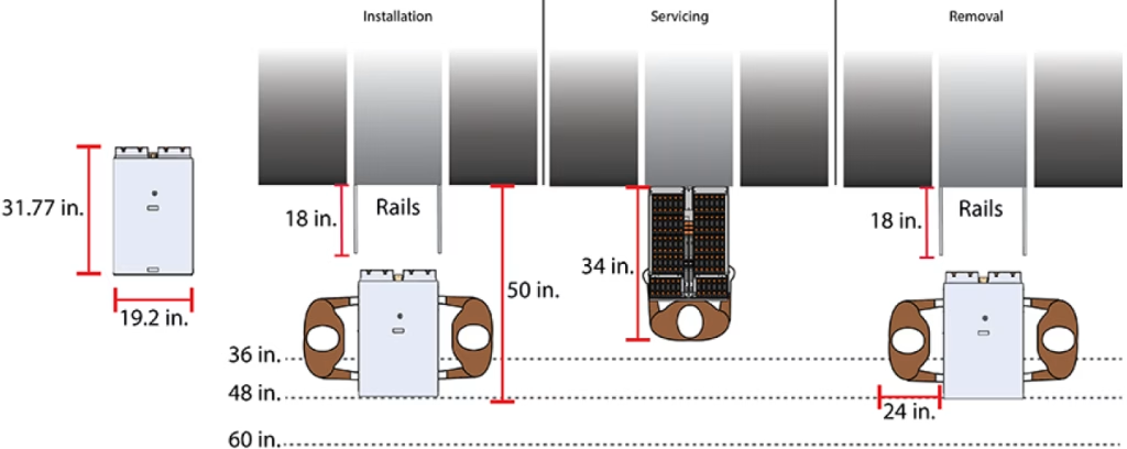
The following section provides specific information necessary to install, service, and remove the R60E Storage Expansion. The installation of the R60E Storage Expansion requires two people and a space of 1270mm / 50in. in front of the installation space. The servicing of the enclosure requires one person and a minimum of 863.6mm / 34in. of space in front of the installation space. The removal of the enclosure requires two people, 914.4mm / 36in. of space in front of the installation space, and 24in. on either side of the enclosure for two people to remove the enclosure.
Installation Requirements #
The proper installation of the Arxys VideoX Enterprise Appliance will require the following hardware and resources:
- Keyboard and mouse.
- Display monitor capable of 1024×768 resolution with a Standard VGA connector
- Two 110V-240VAC power ports (Preferably on different sources, UPSs, or circuits)
- Gigabit Ethernet connectivity
- Network IP address
- Available space in a computer equipment rack depending on the Arxys VideoX Enterprise Appliance configuration.
- Available ports in an uninterruptable power supply (UPS).
Unpacking the VideoX Enterprise Appliance #
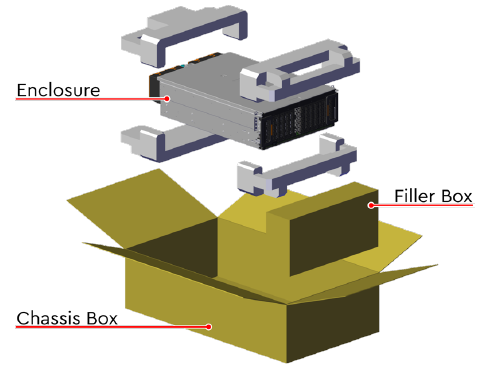
The Arxys VideoX Enterprise Appliance should be carefully removed from its shipping box. Inspect the Arxys VideoX Enterprise Appliance and make sure that it was not damaged during shipping and transport. Adjustable sliding rails used to mount the Arxys VideoX Enterprise Appliance server into a standard computer equipment rack are also included.
Arxys VideoX Enterprise Appliance R60E NVR #
- Cut the tape sealing the box and open the box
- Pull the rail kit box up and out. Set aside.
- Pull the top front and rear cushions up and out of the box.
- Lift the system up and out of the bottom cushions and place on an appropriate work surface.
- Remove the system from the plastic sleeve.
- Replace all packing material into the box.
Arxys VideoX Enterprise Appliance R60E Storage Expansion #
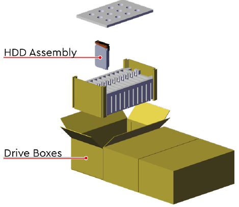
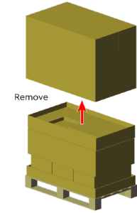
- Remove the top cap and set aside

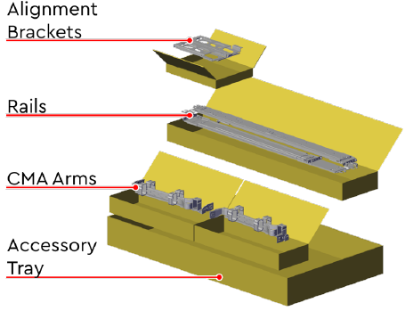
- The accessory tray will be accessible. Remove the rail box, CMA arms, top cover alignment brackets, and all other accessories.
- Open the chassis box and remove the top cushions from the front and rear of the chassis. With assistance and WITHOUT using the system handles, remove the chassis from the chassis box and set it aside.
The chassis weight without HDDs is 44Lbs / 20 kg. To avoid injury the chassis should be team lifted
Do not lift the chassis by the system handles. The handles are designed only for sliding the chassis out of the rack on its rails. - Open the drive boxes and verify their contents. Depending on the version of Storage Expansion being unpacked, the boxes should contain twenty drive assemblies each. Leave the assemblies in their respective boxes until they are installed in the chassis.
Arxys VideoX Enterprise Appliance R60E NVR Rail installation. #

- Slide the inner rail out until it clicks and locks into the extended position.
- Pull the white locking tab forward, then pull out the inner rail.
- Keep track of which inner and outer rail pairs.
- Repeat these steps for the rail for the other side.
Attaching the inner rail to the system #

- Align the right hand side inner rail key holes with the posts on the side of the system. The BLUE release tab should be oriented towards the front of the system.
- Press the inner rail so that it is flush with the system, then slide the inner rail towards the back of the system.
- The inner rail will click and lock into place. Make sure all keyholes are secured on all pins.
- Use the M4x4 fasteners to completely secure the inner rails to the system.
- Repeat steps 1 through 4 for the other side.
Installing the outer rails in the rack #

- Check the hole type on the rack posts. The rackmount rail kit is shipped preconfigured for 9.5 square hole racks.
- The rackmount rail can be changed for use with rack posts using either 7.1 (B) round hole or M5 (C) threaded. See the above image for instructions on what components are required for the conversion.
- Align the front of the (marked FRONT BRACKET) outer rail to with the rack post.
- Pull the outer rail straight forward until the rail locking clip engages.
- Extend or collapse the back of the outer rail and repeat steps 3 and 4 to secure the back of the outer rail to the rack post.
- Repeat steps 3 through 5 for the other side.


Installing the system into the rack #

- Align the inner rails on the system with the outer rails installed in the rack.
- Slide the system back into the rails. There will be a click when the system is a little over halfway in and the system will lock in place.
- Pull or push the BLUE lock release on both sides. The system will now slide all the way back.
- Secure the chassis to the rail using the thumb screws.
- Secure the rear rails to the rack post.
Arxys VideoX Enterprise Appliance R60E Storage Expansion Rail installation #
Installation Overview #
Cable Tray Installation (Optional) #
This procedure provides instructions for installing the cabling tray of a Storage Expansion.
Installation Requirements:
| Tools Required | Long T10 Torx screwdriver with torque measuring capabilities | |
| Parts Required | Cable Tie mount, CMA Standard cable trays, M3 x 8mm T10 Torx Screws | |
| Person(s) Required | 1 | |
| Time to Complete | 15 minutes |
Step 1
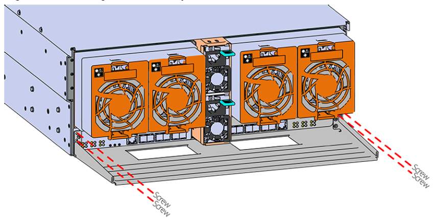
Secure the cable tray onto the enclosure using the included M3 x 8mm T10 Torx screws and the Long T10 Torx Screwdriver. These screws should be tightened to .33-.56 Nm / 3-5 in-lbf.
Rails Installation #
This procedure provides instructions for installing the rails for a Storage Expansion
| Tools Required | Long T15 Torx screwdriver with torque measuring capabilities, level, | |
| Parts Required | Low-Profile M4 x 3.2mm Philips screws, M5 x 12mm T15 Flat Head Torx screws, Screw plate (optional) | |
| Person(s) Required | 1 | |
| Time to Complete | 30 minutes |
Step 1
Remove the inner rail that is nested inside the rack rails.
There are Right and Left rails and they must be installed as a set. Each inner rail will read “R” for the right or “L” for the left embossed on the inside. Each outer
rail will read “R-Front” for the right or “L-Front” for the left. Right and Left refer to when you are facing the front of the rack.
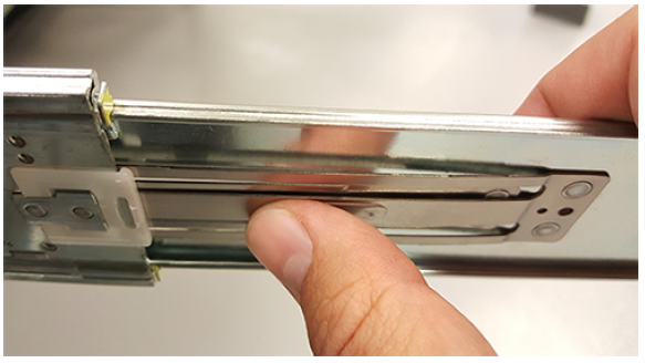
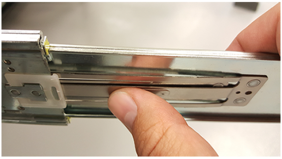
- Start by sliding the inner rail out of the outer/rack rail until the safety latch engages and the inner rail will not extend further. It will only slide one way.
- Press on the safety latch release spring located on the side of the rail and slide the inner rail out the rest of the way.
Step 2
Install the inner rail onto the chassis making sure they are installed on the correct side. Each inner rail will read “R” for the right or “L” for the left embossed on the side that faces away from the chassis. Right and Left are with reference to looking at the front of the enclosure.
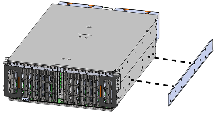
- Orient the inner rails so that the flat side is facing the enclosure and the side with the grooves is facing away from the enclosure.
- Align the keyholes on the inner rail to the mounting pegs on the side of the enclosure and press the inner rail flush against the chassis. If the keyholes don’t line up with the pegs, flip the rail length-wise to see if this will align them.
- Slide the inner rail toward the rear of the chassis to lock it in place. There will be an audible click and the mounting pegs will cover the front part of the keyhole.
- When installing the inner rail onto the chassis, make sure to only use the special Low-Profile M4 x 3.2mm Philips screws provided in the accessory kit with the CMA. These screws should be tightened to .90-1.12 Nm / 8-10 in-lbf using a # 2 Philips Screwdriver. These screws are specially designed for this purpose. Using unapproved screws could cause damage to the slides inside the rail.
- Install the two special low-profile M4 x 3.2mm Philips screws provided to secure the inner rail to the chassis.
- Follow these steps for the second inner rail on the opposite side of the enclosure.
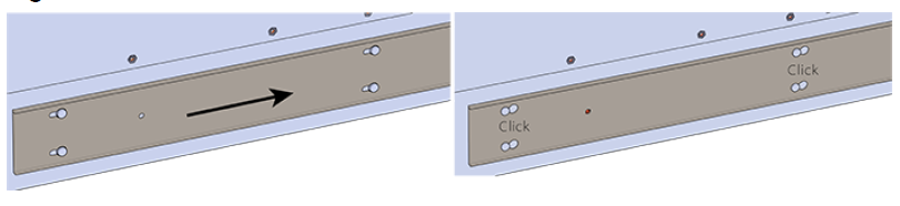
Step 3
Set the vertical rack rail depth to between 24″ and 32″. Ensure that all of the vertical rails are set to the same depth using a tape measure.
Step 4
Install the outer rails into the rack. Pay special attention to which side is being installed. The embossed R is for the right side and L is for the left side. Right and Left refer to when you are facing the front of the rack.
- Move to the rear of the rack.
- Orient the rail so that the word “REAR” that is embossed into the metal of the rail is at the rear end of the rack, and the release latch is facing the inside of the rack posts as shown in the above image.
- Align the rail on the rack posts at the U-height desired for installation. The bottom of the rail will be the lower most U of the total 4U height.
- Pull the rail toward the rack post until the toolless latching mechanism engages the rack. The latching mechanism may need to be pulled open to get around the rack post.
- Move to the front of the rack.
- Align the front of the rail with the holes on the rack posts that will receive the rails and pull the rail toward the holes until the toolless latching mechanism engages the rack.
- Use a level to make sure that the rails are aligned properly.
- Follow these steps for the other outer rail.
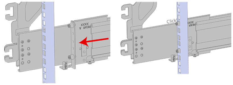
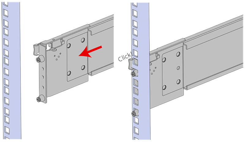
Step 5
Install the rail mounting hardware, starting with the uppermost rack mounting hole of the 4U space on the front of the rack.
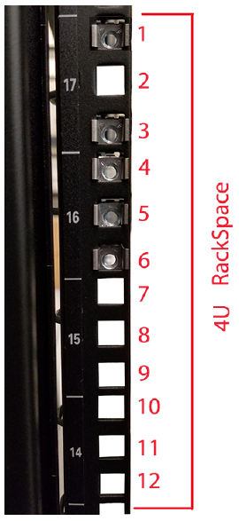
- Install one cagenut at the uppermost mounting hole of the 4U space that the enclosure will occupy.
- If the Storage Expansion will be installed in a rack for shipping purposes, install four more M5 cage nuts in the holes 3-6 of the 4U space. These will receive the M5 x 12mm T15 Flat Head Torx screws that secure the enclosure to the rack with the shipping bracket.
Step 6
Install the rear cover alignment brackets and secure the rear rails.
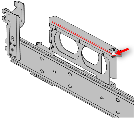
- From the rear of the rack, orient the alignment brackets so that the groove that will catch the cover is facing the inside of the rack.
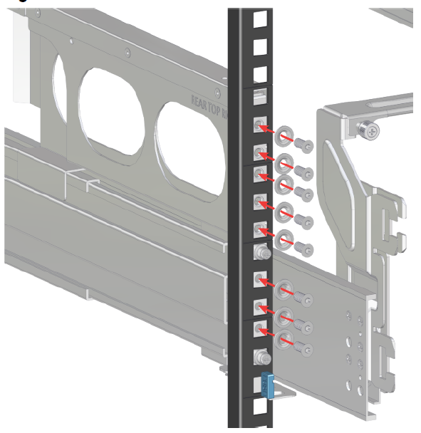
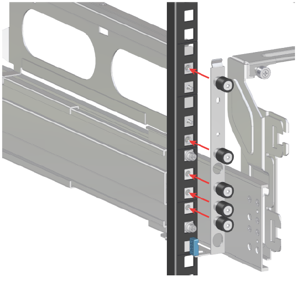
- Attach the rear cover alignment bracket and rear rail to the vertical rack rail. The following examples show two methods for securing the bracket and rail to the rack: individual screws (with washers) or a screw plate.
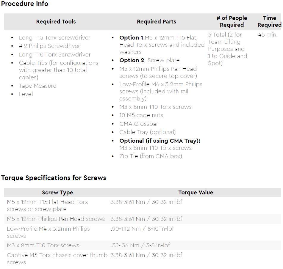
Option 1: Using a Long T15 Torx Screwdriver, install M5 x 12mm T15 Flat Head Torx screws (with washers) to attach the rear cover alignment bracket. The number of required screws will vary depending on the bracket type. Install additional M5 x 12mm T15 Flat Head Torx screws (with washers) to attach the rear rail to the rack posts. Screw locations are shown in the above image. Tighten the rails screws to 3.38-3.61 Nm / 30-32 in-lbf.
Option2: Using a Long T15 Torx Screwdriver, install the screw plate to attach the rear cover alignment bracket and the rear rail to the rack posts. The screw locations are shown in the above image. Tighten the rail screws to 3.38-3.61 Nm / 30-32 in-lbf.
Step 7 #
Install the two rack latch brackets at the front of the rack.
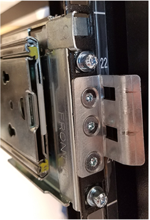
- Orient the brackets so that the screw holes are between the two pins supporting the outer rails as shown in the following image. There is a left and a right. Use the image above as a guide for how to orient this bracket and mirror it for the other side. Notice the increased distance between the top two screw holes and the lower screwholes and the flange being oriented on the outside.
- Use 6 of the included M5 x 12mm screws and the T15 Torx screwdriver to install each bracket, 3 screws per bracket.
Chassis Installation #
This procedure provides instructions for installing the chassis of a Storage Expansion
| Tools Required | None | |
| Parts Required | Storage chassis and rails installed in rack | |
| Person(s) Required | 3 total. 2 for team lifting, 1 more to guide and spot | |
| Time to Complete | 10 minutes |
Always install the top cover onto the enclosure before installing the chassis into a rack. Not having the top cover installed may damage the alignment brackets.
Step 1
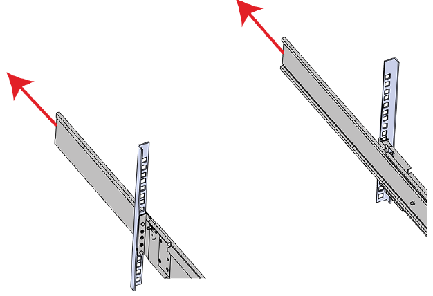
Extend the mid-rails out of the rack so that they are protruding from the front of the rack and the safety latches engage.
Step 2
Install the chassis into the rails.
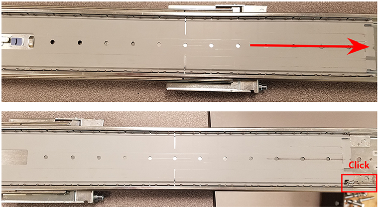
- Extend the bearing plates on the inside of the mid-rails until they are fully forward (detent has engaged). This prevents potential damage due to improper mating of the rails.
- Caution: This step in the installation requires a minimum of 3 individuals to install safely, two to lift and one to guide the others who may have difficulty seeing because the enclosure is in the way. Ensure that the appropriate measures are taken to safely support the enclosure during installation. The enclosure MUST have no drives installed and requires a two person team lift to install. Do not attempt to lift the system if it is fully populated with drives. The only case in which the system may be installed or removed with the drives populated is if the facility has a lift that is rated to handle the maximum weight of the fully loaded system.
Warning: The handles on the front of the chassis are not intended to be used to support the weight of the Storage Expansion . Lifting the unit by the chassis handles or trying to support the unit on the handles can cause them to fail. This can cause serious damage to the unit or serious bodily harm to those handling the unit. Always team lift the chassis by gripping the underside of the unit, and never try to lift a chassis that is filled with drives.
Warning: Do not lift the chassis by the Cable Tray while removing the chassis from the rack OR while installing it into a rack. This can cause serious damage to the unit or serious bodily harm to those handling the unit. Always team lift the chassis by gripping the underside of the unit, and never try to lift a chassis that is filled with drives.
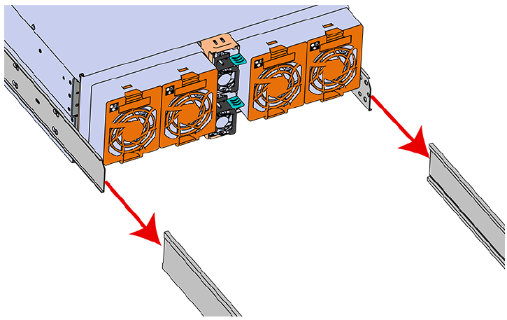
In preparation to perform a team lift, position one individual on each side of the enclosure (to lift) and a third individual standing at the protruding rack rails (to guide the chassis to mate with rack rails). - Team-lift the enclosure until the inner rails (which are attached to the chassis) align with the extended mid-rails (which are attached to the rack), and guide the inner rails on the chassis to mate with the rack rails.
- Once the rails are mated properly, slide the enclosure into the rack until it is stopped by the safety catch on the rails. Push the release lever on the safety latch (located on the side of each of the rails), and push the enclosure the rest of the way into the rack.
Cable Management Arm (CMA) Installation #
This procedure provides instructions for installing the cable management assembly for a Storage Expansion
| Tools Required | None | |
| Parts Required | CMA Standard arm or Dual | |
| Person(s) Required | 1 | |
| Time to Complete | 10 minutes |
Step 1
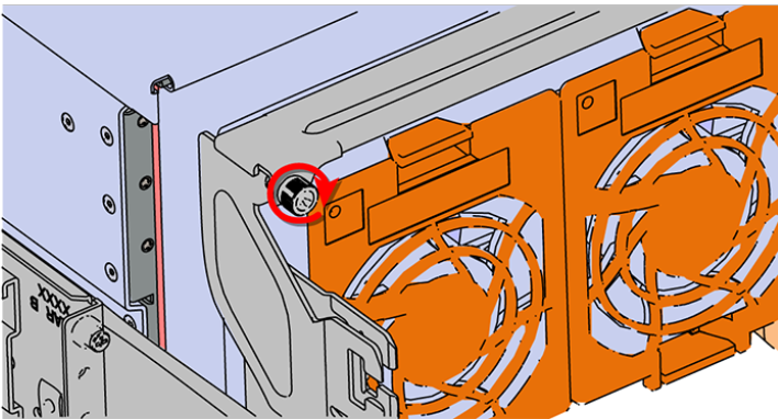
Install the crossbar onto the CMA mounting bracket.
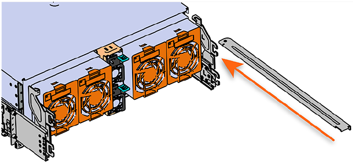
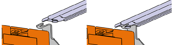
- Align the crossbar with the mounting peg facing down and pointing toward the CMA mounting bracket.
- Insert the peg on the underside of the crossbar into the slot on the CMA mounting bracket.
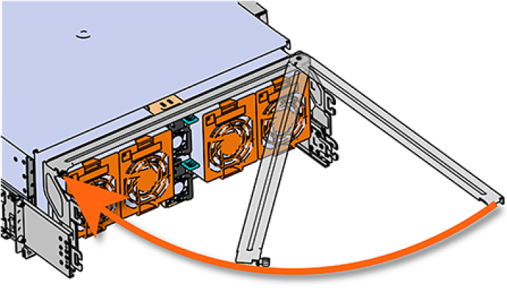
- Swing the crossbar so that the thumbscrew lines up with the mounting hole on the opposite side of the enclosure.
- Press the crossbar against the CMA mounting bracket and secure the crossbar in place by pressing and turning the thumbscrew clockwise until snug.
- Check that the crossbar is fully secured to the CMA mounting bracket by pulling on the bar to ensure it does not move.
Step 2
Install the CMA(s). The CMA has two arms, labeled “upper” and “lower.” The lower arm should have the elbow on the left side and be installed first; the upper arm should have the elbow on the right side and be installed last.
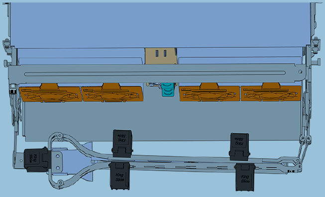
- Orient the CMA so that the elbow is on the left hand side.
- Attach all three of the connectors to the brackets on the rails. There should be one at the elbow side and two at the other end.
- Slowly slide the enclosure forward to ensure the arm is operating properly, then slide it back into the rack.
- CMA Standard: Repeat these steps to install the upper arm with the elbow facing to the right.
Cable Installation #
This procedure provides instructions for installing the data and power cables for a Storage Expansion
| Tools Required | None | |
| Parts Required | Power Cables (C13 to C14) , Data (MiniSAS HD) Cables | |
| Person(s) Required | 1 | |
| Time to Complete | 30 minutes |
Step 1
Cable the CMA(s).
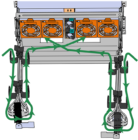
- Unlatch the elbow side of the arm(s) by pressing the blue button labeled “push,” and then swing the arm(s) open.
- Gather the SAS, power, and Ethernet cables for installation. Before cabling, note the above routing patterns for best results.
- Open all of the baskets.
- Connect the Ethernet cable to the Ethernet port, and route the cable through each of the baskets on the arm.
- Connect the SAS cables to the SAS ports, and route them through the baskets one at a time. Make sure to follow the labels to ensure they are connected to the proper ports.
- Connect the power cable to the PSU. Attention: Make sure the power cable is not connected to a PDU. If it is, the system will power up when the cable is connected to a PSU. This is not intended at this stage of installation.
- Attach the cable retention mechanism.
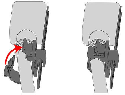
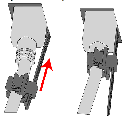
- For the Delta PSU, loop the retention clip around the power cable and pinch it until the clip catches and locks in place.
- Then slide the retention clip forward until it stops near the cable connector. Doing this will ensure that the retention clip functions properly in the event the cable is pulled on for some reason.
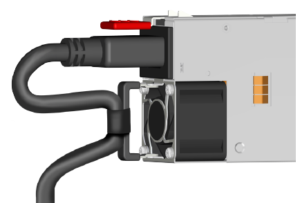
- For the Artesyn PSU, secure the power cable to the PSU handle with the velcro retention strap as shown in the above image.
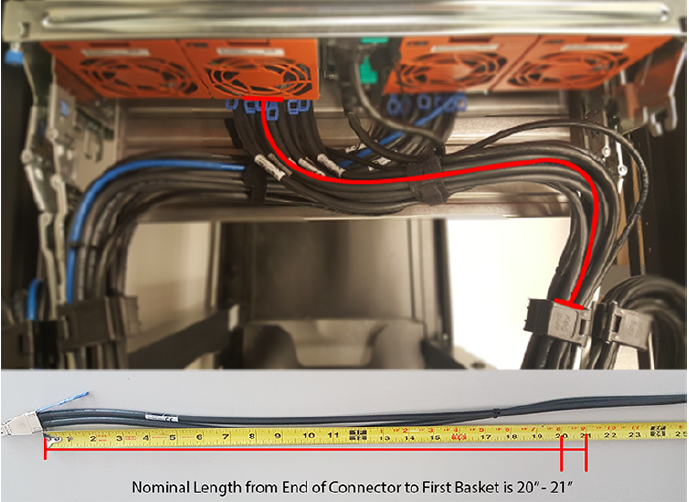
- Route the power cable through each basket.
- Each cable must be given enough slack at the connector end to operate smoothly. Allow 20 – 21 in. (508 – 533.4 mm) between the connector and the first basket.
- Close all of the baskets.
- If the Storage Expansion is being installed in a rack and will subsequently be transported inside that rack, it is important to use the included cable tie to wrap the CMA bundle to ensure it does not get damaged during transport. If the Storage Expansion is instead being installed where it will be operated, skip this step. Remember to remove the cable ties after the enclosure has reached its final operational location.
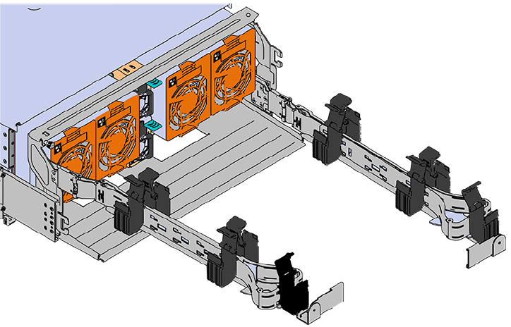
- Reconnect the arm at the elbow to the connectors on the rail.
- Make sure the CMA(s) is in operational position by folding the arm(s) in toward the enclosure and attaching the elbow end(s) to the connector(s) attached to the rail. Verify that all of the cabling is in functional order and does not bind or catch.
- Test for binding in the extension of the arm by gently pulling the enclosure out of the rack, ensuring the cables extend properly and that the system doesn’t bind at all. If it does, examine the point at which the binding occurred and adjust the seating of cables in the baskets, check the connections to the rails, and examine the joints of the arm to ensure that they are all functioning properly
Drive Installation #
This procedure provides instructions for installing drives in a Storage Expansion
| Tools Required | None | |
| Parts Required | 60x 3.5 inch hard disk drive assemblies | |
| Person(s) Required | 1 | |
| Time to Complete | 30 minutes |
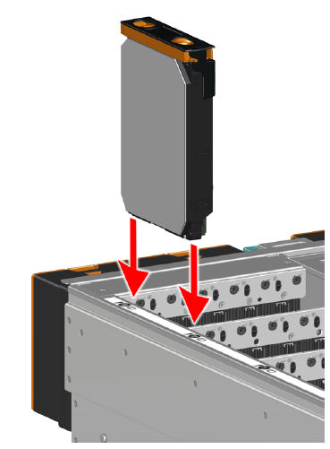
- Pull the enclosure out of the rack until the latches engage
- Align the drive with the empty slot that will receive the hard disk drive assembly.
- Lower the hard disk drive assembly into the slot. Make sure to keep the hard disk drive assembly level so that it does not bind.
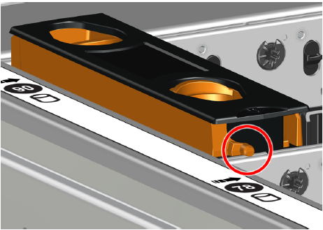
- Lower the hard disk drive assembly until the spring loaded posts on the carrier contact the top edges of the drive slot. This is an intermediate position; the hard disk drive assembly will be fully seated later.
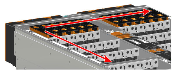
- Repeat this intermediate installation for the remaining hard disk drive assemblies, populating the enclosure from left to right and rear to front.
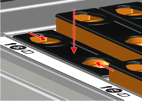
- After all hard disk drive assemblies are installed, pinch the latch release and carefully press downward to fully seat the hard disk drive assemblies into their slots.
- Repeat this action to fully install the remaining hard disk drive assemblies.
- Now that the drives are installed into the chassis, test the installation by sliding the enclosure in and out of the rack a minimum of three times. If the enclosure binds, catches, or displays any incorrect motion or behavior retry the installation of the drives and chassis
Securing the VideoX V4 R60E Storage Expansion to the rack #
This procedure provides instructions for installing drives in a Storage Expansion
| Tools Required | Long T15 Torx Screwdriver | |
| Parts Required | M5 x 12mm T15 Flat Head Torx screws | |
| Person(s) Required | 1 | |
| Time to Complete | 5 minutes |
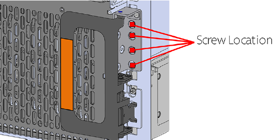
- Install eight (four per side) of the included M5 x 12mm T15 Flat Head Torx screws into the two brackets at the front of the chassis in the following locations.
- These screws should be tightened to 3.38-3.61 Nm / 30-32 in-lbf using a Long T15 Torx Screwdriver.
VideoX V4 R60E NVR to VideoX V4 R60E Storage Expansion Cabling Diagram #
DO NOT POWER ON the VideoX V4 R60E until all Storage Expansion are connected.
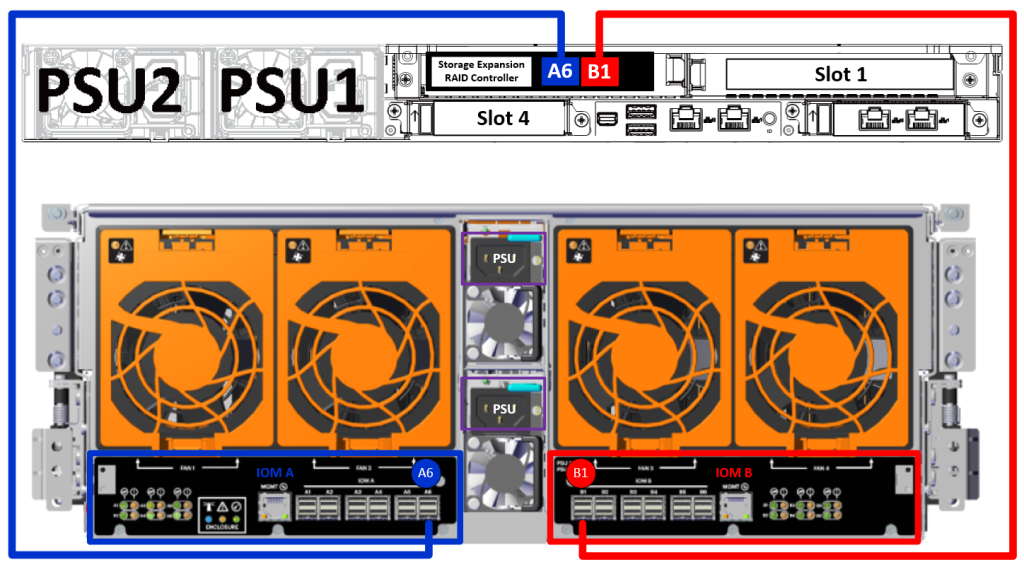
Use a included SAS cable to connect the VideoX V4 R60E NVR A6 port to the A6 port on the VideoX V4 R60E Storage Expansion.
Use a included SAS cable to connect the VideoX V4 R60E NVR B1 port to the B1 port on the VideoX V4 R60E Storage Expansion.
Connecting Cables and Powering On #
VideoX V4 R60E NVR and VideoX V4 R60E Storage Expansion are factory matched and configured. Pay close attention to the labeling on the systems and make sure the matched systems are installed together to avoid delays in deployment.
- Connect the VideoX V4 R60E NVR A6 port to the A6 port on the VideoX V4 R60E Storage Expansion.
- Connect the VideoX V4 R60E NVR B1 port to the B1 port on the VideoX V4 R60E Storage Expansion.
Refer to the diagram above for the location and description of the various connectors.
The VideoX V4 R60E Storage Expansion MUST be powered on first!
Powering on the VideoX V4 R60E Storage Expansion #
- Simultaneously plug both of the enclosure power cords into a PDU to power the enclosure.
Caution: The VideoX V4 R60E Storage Expansion can only be plugged into high line (200-240 VAC) power. If the unit is plugged into low line (110-127 VAC), the PSU will report a “Critical” state when status pages are queried using SES. In this case, the enclosure will power up, but the drives will not. The enclosure will remain in low-power mode. - The VideoX V4 R60E Storage Expansion will power on immediately.
- Wait for 5 minutes before powering on the VideoX V4 R60E NVR
Cabling and Powering on the VideoX V4 R60E NVR #
Make the following connections:
- Connect the VideoX V4 to either a KVM or a dedicated keyboard/mouse and monitor. The keyboard and mouse can be connected to any USB port. It is recommended that the monitor be connected to the VGA port in order to maintain the remote KVM functionality in IPMI.
- Connect the VideoX V4 to your network by plugging an Ethernet cable into one of the Ethernet ports. Verify that the appropriate switch port is utilized.
- For out of band management connect an Ethernet cable to the IPMI ports. This is high recommended.
- Connect a power cable to each power supply. Verify that the power cable is connected directly to a UPS or through an appropriate power distribution unit.
- When power is supplied, the system will go through a low level test before allowing the system to power on. This can take up to 45 seconds. While the system is performing its low level test the Power LED on the front panel will blink.
- Make sure the VideoX V4 R60E NVR is correctly cabled to the VideoX V4 R60E Storage Expansion
- Once the power LED turns off, the system can be turned on by pressing the power button.
- Allow the system to boot in the operating system without interruptions
Revealing the Windows Product Key #

The product key is found on the Microsoft® Certificate of Authenticity (COA) label located on the front left corner of the appliance. Similar to the removable material commonly found on lottery tickets or prize vouchers, this concealment panel is designed to protect the consumer’s product key from being obtained and used by unauthorized individuals. Carefully scratch off the concealment coating with a fingernail or coin to reveal the entire product key. Damaged COAs are not covered under warranty.
Log Into Windows For The First Time #
The Arxys VideoX Enterprise Appliance is configured with the Microsoft® Windows® Server 2022 (Microsoft® Windows® Server 2019 optional) operating system. The Windows operating system requires an initial configuration when used for the first time.
When the Arxys VideoX Enterprise Appliance is first powered the Microsoft® Windows® Server 2022 will begin booting. Please do not interrupt or power off the Arxys VideoX Enterprise Appliance during this process. The Arxys VideoX Enterprise Appliance may automatically reboot as the final configuration is applied to the system.
After the system reboots the Windows® Server 2022 operating system will load. Follow the onscreen instructions to continue. Windows® Server 2019 setup will be similar.
VideoX Enterprise Appliance OS Setup #

At the “Hi there” screen select the correct home country/region, the preferred app language, and the keyboard layout to use. Once correctly selecting the options needed click the Next button to continue

At the “It’s time to enter the product key” screen enter the product key that is on the Microsoft® COA label attached to the system. The COA label is attached on the top front left corner of the system. It may be required to scratch off some of the protective/privacy silver coating to reveal the entire product key. Click on the “next” button to continue.
See section Revealing the Windows Product Key https://www.arxys.com/docs/videox-v4-r8e-and-r12e/#22-toc-title If the product is not available (remote install) click the ‘Do this later’ link to continue. Note that Windows will not activate until the product key is entered.

At the “License terms” screen review and accept the Microsoft® Windows® Server 2019 license agreement.

At the “Customize settings” screen, set a password for the local administrator account. The password should:
- Have a minimum length of 7 characters.
- Meet the complexity requirements. See https://technet.microsoft.com/en-ca/library/cc956977.aspx for details
- Do not lose this password. This password will be needed to log into the system in order to continue the configuration of the server.
Type in the password twice as indicated on the screen and click on the “finish” button to continue. Arxys Support cannot reset this password and there is no default password configured.

Press CTRL+ALT+Delete to unlock the system. Type in the credentials created in the previous step.
Once logged in, the system will auto start the VMS installer (if specified) for the integrator to install and configure.
Completing the installation of WDRM #
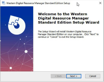
Western Digital Resource Manager (WDRM) is an optional management utility that allows for visual monitoring and maintenance of VideoX V4 R60E Storage Expansion.
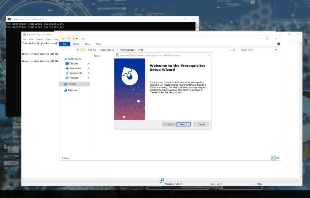
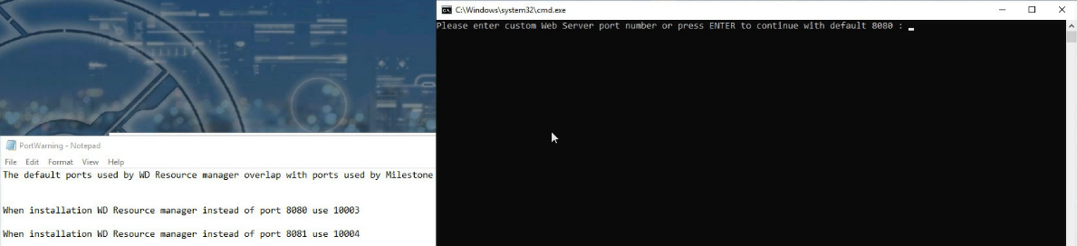
- When logging in for the first time, the WDRM Prerequisites setup wizard will auto start. A special note will also auto open indicating the recommended network ports to use for WDRM.
- It is recommended that ports 10003 and 10004 be used for WDRM. The default ports overlap with various VMS default ports.
- It is recommended that ports 10003 and 10004 be used for WDRM. The default ports overlap with various VMS default ports.
- Close the command prompt window by clicking on the “X” on the top right corner
- Close Server Manager if it opens.
- At the WDRM setup wizard, click NEXT
- Click NEXT again
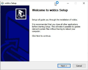
- The WDDCS Setup will start.
- Click NEXT
- Review and agree to the terms
- Click NEXT
- Click NEXT
- Click FINISH
- The WDRM Setup wizard will start
- Click NEXT
- Review and accept the terms
- Click NEXT
- Click NEXT
- Click INSTALL
- After a few moments a command prompt will open and ask which network ports WDRM should use.
- Enter 10003 and press enter
- Enter 10004 and press enter
- After a few moments the command line prompt to auto close.
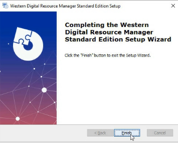
- Click FINISH
Checking RAID Health #
Arxys VideoX Enterprise Appliance will ship with storage resources pre-configured if the configuration is specified at the time of ordering. Before utilizing the storage resources provided by the Arxys VideoX Enterprise Appliance, the health of the solid-state disk (SSD), hard disk drives (HDD), and RAID arrays should be verified.
Video Storage RAID – WDRM #
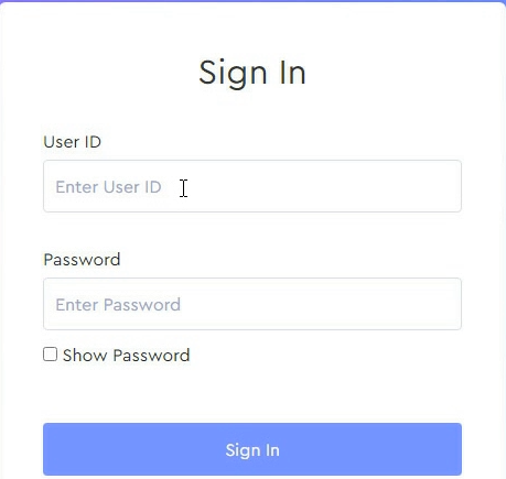
WDRM can be used the check the status and RAID health of the storage expansion.
- Log in to the Arxys VideoX Enterprise Appliance as “administrator” (using the password that was configured during first boot)
- From the desktop or start menu locate the WD Resource Manager shortcut. Double–click the shortcut to start the utility.
- Accept the security warning to continue to WDRM
- Log in to the utility as “urmadmin” with the password “admin@123” . Allow the utility to load.
- Use the utility to verify the RAID array and health of the expansion chassis.

Video Storage RAID – LSA #
Arxys VideoX Enterprise Appliance ships with the LSI Storage Authority (LSA) utility pre-installed. This utility will be used to verify the status of the HDDs configured for video storage. A shortcut is placed on the desktop. It can also be accessed via the start menu. LSA uses the local web browser. Use any local or domain administrative account to log in.
- Log in to the Arxys VideoX Enterprise Appliance as “administrator” (using the password that was configured during first boot)
- From the desktop or start menu locate the LSI Storage Authority (LSA) shortcut. Double–click the shortcut to start the utility.
- Log in to the utility as “administrator” (using the password that was configured during first boot). Allow the utility to load.
- The status of the raid controller and its volumes are displayed on the top-left corner. The status should display “Optimal.” If the status displays anything other than “Optimal” immediately stop and power off the system. Then verify that:
- Only the drives labeled for use with the system being installed are installed in the system.
- ALL of the drives labeled to use with the system being installed are installed in the system.
- The drives should be installed in the system BEFORE powering on the system.
- Background operations are also displayed in the same menu under the raid controller ID. “Check consistency” and/or “initializing” procedures run on schedules to preemptively correct any errors. If “Check Consistency” or “Initializing” operations are in progress, the video storage array remains in an optimal condition.
- After verifying the optimal status of the video storage array, exit the utility.


Configuring Network Settings #
Your organization network administrator should be able to provide you with the information required to configure the network on the Arxys VideoX Enterprise Appliance. Generally, the information required is: IP address, subnet mask, gateway, and DNS server. Some networks run the DHCP protocol which will assign all of the above settings automatically. It is recommended that the Arxys VideoX Enterprise Appliance be configured with a static IP address.
- Click on the start menu, followed by settings
- At the Windows Settings screen click on the “Network & Internet” section
- Click on the Change adapter options link
- The network connections of the system are displayed. From here you can configure a static IP address. For more information see the Windows Help and Support files.
Video Management Software #
If specified, Arxys preloads VMS installers for in order to speed up the deployment and setup process. The preloaded VMS installers are located in the folder:
C:\ArxysSupport\VMS
Browse to the VMS folder and double click on the VMS installer application to start the installation process. Follow the onscreen instructions to complete the setup.
Arxys VideoX Enterprise Appliance typically ships with a preconfigured volume to use for video surveillance video called “VideoStorage” and is typically configured in Windows as drive “D:\” The VMS that is being installed should be configured to store video files here.
SQL Server and SQL Express Installation errors #
If you install any version of SQL Server on a Windows Server 2022 device and you may see errors related to installing or starting the Database Engine Services component of SQL Server. Logs will show “SQL Express failed. Error code = -2061893606′”
Additional information can be found here https://learn.microsoft.com/en-us/troubleshoot/sql/database-engine/database-file-operations/troubleshoot-os-4kb-disk-sector-size.
Arxys has internally tested the add ForcedPhysicalSectorSizeInBytes resolution proposed by Microsoft successfully
Additional information regarding this is also available from Milestone here: https://supportcommunity.milestonesys.com/s/article/XProtect-fails-to-install-Windows-11-InstallationAdapterException-error-code-2061893606-troubleshooting?language=en_US
Lastly some VMS installation packages may have custom SQL initialization files that may not work for all environments. For these cases, it is recommended that the appropriate version of SQL be installed prior to installing a VMS. Once SQL is installed and confirmed to be functioning, install the VMS and have it use the existing SQL server.
Milestone VMS Best Practices #
Do not run SMART Client on a recorder.
Do not leave the Management Client open to views that display video feeds. This will cause unnecessary additional load on the recorder.
If more than 300 cameras are on the site, SQL Standard must be used. SQL Express is not recommended for a deployment this large.
Do not exceed 20,000 cameras/day per storage profile. See https://supportcommunity.milestonesys.com/s/article/when-should-I-use-archive-storage?language=en_US
This may require RAID reconfiguration which can be done using LSA.
Configure your maximum recording and archive retention limits so that video is deleted upon a set schedule, and not when the hard disk drive reaches its maximum capacity. For best performance, we recommend to maintain at least 15% of the drive free.
Configure the recording and archive hard drives to have a cluster size (block size) of 64K or higher.
Ensure RAID stripe size is set to 512K or higher.
Disable real-time antivirus scanning; instead choose to scan the system based on a schedule. Consult the XProtect Administrator’s Manual regarding which files/folders and processes to exclude. You can also find more information about anti-virus scanning and XProtect in KB 1004, “Configure anti-virus software on XProtect systems (best practices).”
If your surveillance server storage has one single storage array, do not archive. (See the corresponding KB 3614, “When should I archive?”)
Disable any non-essential Windows tasks and processes that affect the file system. These could include the indexing service and the volume shadow copy service. Also make sure to never use Windows drive compression as it will slow down all write-to-disk operations.
In the RecorderConfig.xml file, the “chunk_files” buffers should be set to 64K
Avigilon VMS Best Practices #
Before starting the ACC setup and installation it is recommended that the built in Windows Server 2019 AntiVirus software (Windows Defender or any additional AntiVirus software loaded by the end user) be temporarily disabled or suspended. During the ACC installation a Storage Configuration will create a storage layout. If Windows Defender is enabled this process will take multiple days to complete. https://help.avigilon.com/acc-setup/en/setup/configure-antivirus.htm
Do not leave the ACC client open on the system with a view tab open. This will cause unnecessary additional load on the recorder. https://assets.avigilon.com/documents/avigilon-nvr5-datasheet-en-rev3.pdf (see no local viewing)
If using analytics, verify that the GPU included with the system is operation in TCC mode.
Windows Activation Without Internet Access #
In the event that Internet access is not possible the Windows® Activation procedure can be completed via the use of the Microsoft® Windows® Activation telephone hotline.
- Log into the system as a member of the administrative group.
- From the Start Screen, Type ‘slui 4’ click on the icon to run the wizard.
- Select the nearest location from the drop-down menu and click “Next.”
- Call the phone number displayed and follow the promptings. You will have to provide the “Installation ID” and will receive a “Confirmation ID.”
- Click “Next” and follow the onscreen instructions to continue and complete the activation process.


IPMI Configuration and Usage #
Arxys VideoX Enterprise Appliance include Intelligent Platform Management Interface (IPMI) 2.0 compliant interface that allows you to monitor, control, and manage a remote server from the locally or remotely via the local network. With IPMI you can completely and efficiently monitor your server in real time. IPMI includes remote KVM (keyboard, video, mouse) support.
In order to utilize IPMI you need:
- A configured BMC
- Available network port (RJ-45)
- Modern Web Browser (Edge, Chrome, Firefox
Configuring IPMI Network in the BIOS #

- Plug in a network cable into IPMI port on the server. See the appliance overview section for more details on the location of the port.
- Power cycle the server (remove AC power, wait 5 seconds, and then plug the AC power back in)
- During POST, enter the BIOS by pressing key.
- Once in the BIOS navigate to the “Server Mgmt” menu using the right arrow key
- Then select the BMC Network configuration from the options
- By default, IPMI will grab an IP address from DHCP. If the IP assigned is acceptable note the IP and skip to REMOTELY ACCESSING THE SERVER
- To change to a static IP; select the Configuration Address source and press ENTER.
- From the sub menu select Static and press enter
- Use the new options to set:
- The IP address for IPMI
- The subnetmask of the network
- The router or gateway address for the network
Press escape and navigate to the “Exit” menu. Select “Save Changes and Reset” and press <enter>. The system will reboot.


Remotely accessing the System #
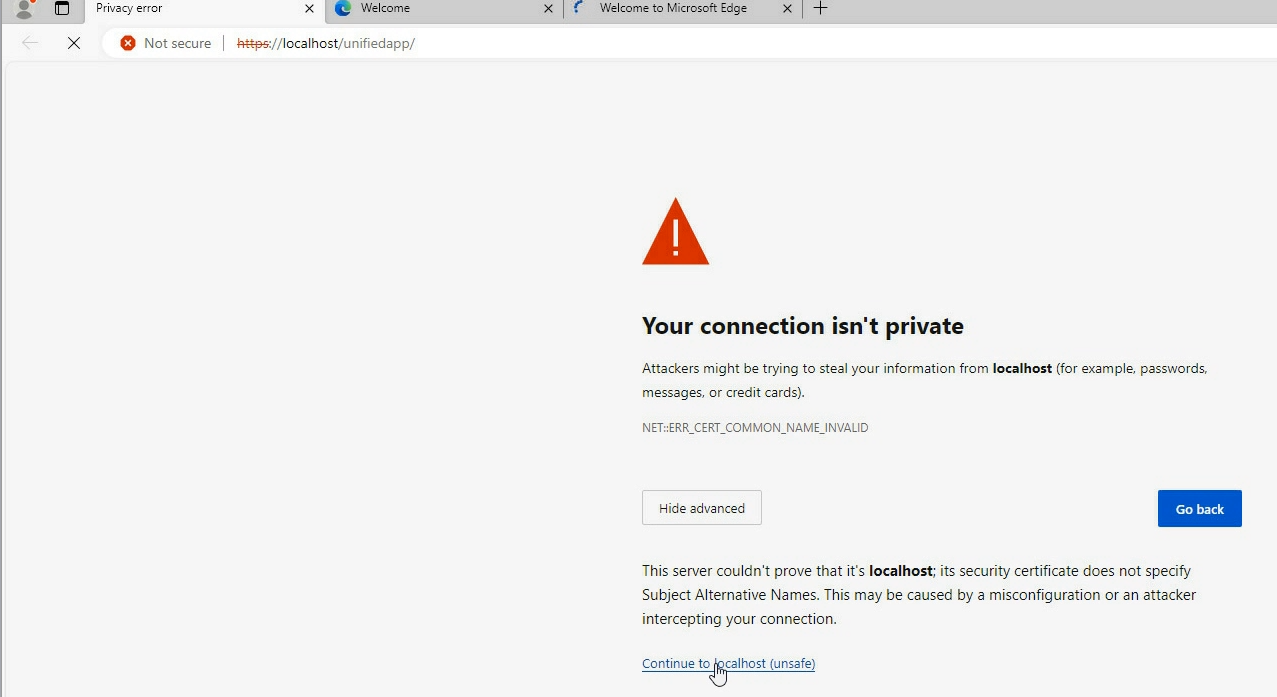
- Utilize a web browser to browse to the IP address set listed in the IPMI section of the BIOS making sure to start with https://
- Example: https://192.168.1.100
- Example: https://192.168.1.100
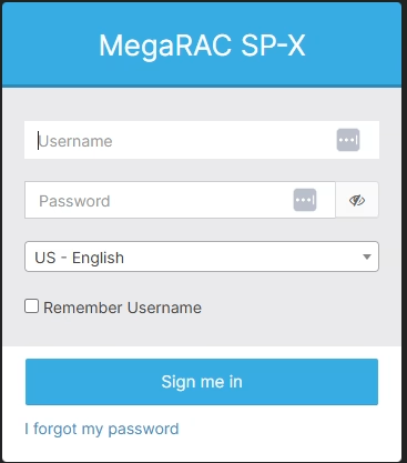
- A log in prompt will be presented.
- IPMI is now configured and accessible.
- The default user is ‘admin’ the password will be unique for each system. The password is located on a silver label attached to the top right-hand side of the system near the serial number.
Starting A Remote KVM Session #
In troubleshooting or remote managing the system it may be required to establish a remote KVM sessions with the system. A remote KVM sessions will simulate having a keyboard, video display, and mouse connected to the system. This will allow you enter the BIOS of the system and other pre-OS sections of the system. Not that post operating system video will ONLY be displayed if there is a display connected to the VGA connector of the system.
- Establish a web GUI session using https://IP_address
- Log in. The default user is ‘admin’ the password will be unique for each system. The password is located on a silver label attached to the top right-hand side of the system near the serial number.
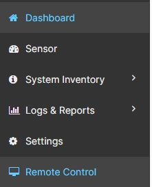
- Locate the left hand side menu and click on the Remote Control section.
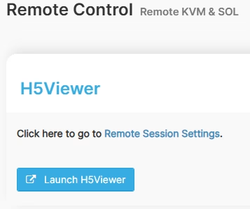
- Click the “Launch H5Viewer” button. A new window will appear
- A remote KVM session is now established.
Reviewing System Health via IPMI #
- Connect the the IPMI web console. See section Remotely accessing the System for RevG Systems
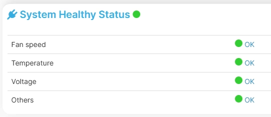
- From the dashboard look for the “System Healthy Status” section on the right side. This will indicate the general status of the system.
- For more detailed information click on the “Sensor” section listed in the menu on the left hand side
- Scroll through the sensors to see the temperature, voltage, and other readings of the various sensors in the system.
Maintenance #
Although the Arxys VideoX Enterprise Appliance requires minimal maintenance, basic maintenance will increase the lifespan of the hardware. Like the majority of equipment installed in a computer hardware rack, the Arxys VideoX Enterprise Appliance uses a front intake and rear exhaust cooling design. It is very important that the airflow of the cooling system is not blocked or hindered in any way. The most common way that a server’s cooling system is blocked is by the accumulation of dust in the front air intake passages of the server. At regular intervals the dust should be wiped from the front bezel. Additionally, using compressed air to blow out the dust that has settled on the drives bays will assist in keeping the Arxys VideoX Enterprise Appliance’s cooling system running at its highest efficiency.
System Health #
The health of the system can be checked via IPMI
- Establish a web GUI session using https://IP_address
- Log In
- From the dashboard click on the Sensor Readings button located at the top right of the screen.
- A list of all system sensors and their status will be displayed
Capturing System Logs #
It may be necessary to capture logs in order to start a support ticket with Arxys. For instructions on how to do this see https://www.arxys.com/docs/capturing-logs-2
Compatible Hardware #